.. Don't know what the zener does.. QUOTE]
As far as I am aware, the zener diode clamp (in series with the normal diode) is there to reduce the drop out time of the relay, by shutting off the relay coil back e.m.f. circulating current much sooner than it otherwise would.
The zener is shown the wrong way round in posts 131,132.
Brian.
Ref: Doug Self. Muting Relays. EW July 1999.
Hello Brian and greetings from soggy Tasmania!
My original try at that zener is shown in post 139, it shows the zener in reverse bias. Anyway, I have just taken delivery of Mr. Self's "Self on Audio" .
I didn't know the origins of the circuit so your reference put me right in the hot-seat.
This is the type of valuable information that can shared amongst fanatics like us!
Mate, I hope the sun is shining on the other side of the Globe.
Thanks again Brian and bye for now. Sincerely, Phil
DC Offsett protection
Do any of you fellows know what size the back emf spikes of a relay coil makes (piece of string, I know, but roughly).
The answer is important to me because my mosfet will handle 200v.
Mr Self says that; of four selected relays that he tested, the maximum spike was 120v.
If this is the case with my relay then I can loose all four diodes, in particular the 4007's which delay the turn off time by a factor of (minimun) four times! Therefore they exist to protect the 'smaller' transistors that may be used in other applications.
Relays and back EMF is a bit of a mystery to me, but is seems unlikely that a 200V MOSFET would be in mortal danger.
I do have a copy of EW July 1999. I will scan Doug Self's article "Muting Relays" tomorrow and post it here.
His answer to the problem is to put a Zener in series with the diode. That will clamp the voltage to sane limits.
I do have a copy of EW July 1999. I will scan Doug Self's article "Muting Relays" tomorrow and post it here.
His answer to the problem is to put a Zener in series with the diode. That will clamp the voltage to sane limits.
Last edited:
Does this one work in the simulator?
The short answer is "no."

Even with the 0.1 ohm resistors deleted.
The biasing seem to be out of kilter.
Attachments
Last edited:
Thankyou all
Hello all. I am taking a step back for a day to read Mr Self's chapter on Output relays, I have already figured a heap of stuff out; including my old oscilloscope - I can now get a picture of that back emf on my 5v coils it seems to go down to -150v or thereabouts, but only lasts for around 1ms.
If I use higher voltage relays I can run the whole job of my 55v rail.
I will also detect loss of AC in order to mute on power down.
Indeed the zener does run in reverse bias, and NO I wont leave any diodes out.
I'm starting to get it now Brian, I was a little bit baffled by a few of the things you told me, but reading Mr Self's book has opened my eyes. Wouldn't be the first time I've been stumped like that!
Back soon, and thanks, Phil
good decision.If I use higher voltage relays I can run the whole job of my 55v rail.
24Vdc rather than 12Vdc would be even better.
A pair of series connected 24Vdc relays running with a voltage dropping resistor from 55Vdc would be an excellent low current circuit to use.
The short answer is "no."
Even with the 0.1 ohm resistors deleted.
The biasing seem to be out of kilter.
Oooooooh, I am so embarrassed.
Please ignore the above post. The amp works fine.
In my simulation I started with the previous version of the circuit where I was exploring the workings of the VI limiter. For this I had a half ohm load. Which I neglected to change.

With an eight ohm load the design is OK.
All is peaceful in the barnyard.
Dont be silly my friend, you have been vigorously helping a stranger with a project he is ill-equipped to deal with, and one thing that I am very very greatful for is the doubt you put into my mind about that VI Limiter. No other member spoke of this UNTIL you pointed it out - So I owe you one.
Do you know, half the amps I look at have that so-called vi circuit installed and the owners probably think they are safe when they leave home and their kids start playing their Hip-Hop at level 10 - poor buggers. Not to mention the fuzz that it causes at higher levels of gain.
I always test each 'module' of a project before hooking it up, and once I get my boards finished off, I will be seeking advice on how to test the dc offsett and AC detect relays. Good realys are expensive for good reasons, for example some act faster and last longer than others. This is one component that I will pay good money for, Potter and Brumfield make some real corkers, I have one here now and it is a work of art visually and mechanically.
As another member has suggested I am going to use much lighter and faster fuses on the rails in conjunction with the DC detect.
PS. I bought a copy of Douglas Self: "Self on Audio" it is an excellent resource.
We will talk again soon, and stay away from the 'flake'. - Pure sugar! Eat Shark instead.
Cheers and bye for now. Phil
Can this amp be further optimised?
Hello and greetings from Tassie.
I have built one channel of my new amp’ and it worked first time!
In the past I have thought, that because the design has been in the pipeline for so long, that my scepticism would ‘can’ the project.
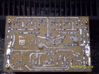
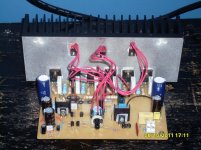
The amp is now running and seems to work properly to the best of my knowledge! (See pictures of board layout below).
At this stage I want to thank all of the contributors who have ‘stuck-with-it’ and helped along the way. Particularly Selim, Ingenius, Tekko & Andy-T. There were many others who added significantly also; with hints and tips, some of which the aforementioned and myself had missed in the re-hash of the design.
I would like to present some measurements and observations of the unit and call for comments and suggestions that will adjust & improve the performance of the module.
Here is what I have so far;
· The power supply puts out +56/0/-56VDC without a load.
· A sine wave of 1V(pk_to_pk) applied to the input comes out the opposite end at 50V(pk_to_pk)
· The bias arrangement (vbe multiplier) gives a very small range of adjustment – between ~ 1V and 1.2V
· The output stage emitter resistors (0.22r)show a voltage drop of; ~ 100mV for a 50Hz sine wave; and 75mV for a sine wave of 1kHz.
· Of most interest to me is the apparent lack of Iq in the case when I switched off my signal generator (which was still connected to the input) - the amp was idle, but still turned on. In this case the voltage drop across the output emitter resistors fell to a level indestinguishable from zero volts but perhaps 1mA was trickling through. Is this something that must be ‘fixed’ in order to use the amp sensibly as part of a stereo?
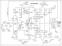
I will re-post the new schematic and a couple of photos of the amp module itself. Please excuse the sloppy solder-job, I am learning to use lead free and it doesn’t seem to flow real well for me and my old soldering irons. Also the tips of the soldering irons seem to pick up an inpenetrable and invisible film that holds the heat inside the tip until you scrape it off with a stanley knife – steel wool won’t touch it.
Cheers, P.E.
Hello and greetings from Tassie.
I have built one channel of my new amp’ and it worked first time!
In the past I have thought, that because the design has been in the pipeline for so long, that my scepticism would ‘can’ the project.
The amp is now running and seems to work properly to the best of my knowledge! (See pictures of board layout below).
At this stage I want to thank all of the contributors who have ‘stuck-with-it’ and helped along the way. Particularly Selim, Ingenius, Tekko & Andy-T. There were many others who added significantly also; with hints and tips, some of which the aforementioned and myself had missed in the re-hash of the design.
I would like to present some measurements and observations of the unit and call for comments and suggestions that will adjust & improve the performance of the module.
Here is what I have so far;
· The power supply puts out +56/0/-56VDC without a load.
· A sine wave of 1V(pk_to_pk) applied to the input comes out the opposite end at 50V(pk_to_pk)
· The bias arrangement (vbe multiplier) gives a very small range of adjustment – between ~ 1V and 1.2V
· The output stage emitter resistors (0.22r)show a voltage drop of; ~ 100mV for a 50Hz sine wave; and 75mV for a sine wave of 1kHz.
· Of most interest to me is the apparent lack of Iq in the case when I switched off my signal generator (which was still connected to the input) - the amp was idle, but still turned on. In this case the voltage drop across the output emitter resistors fell to a level indestinguishable from zero volts but perhaps 1mA was trickling through. Is this something that must be ‘fixed’ in order to use the amp sensibly as part of a stereo?
I will re-post the new schematic and a couple of photos of the amp module itself. Please excuse the sloppy solder-job, I am learning to use lead free and it doesn’t seem to flow real well for me and my old soldering irons. Also the tips of the soldering irons seem to pick up an inpenetrable and invisible film that holds the heat inside the tip until you scrape it off with a stanley knife – steel wool won’t touch it.
Cheers, P.E.
Attachments
Firstly, be very careful when altering anything around the vbe multiplier if you are the slightest bit unsure. Maybe use a bulb tester.
Assuming the circuit is built correctly then it may be there is insufficient range on the bias pot.
To develop a bias voltage across the vbe multiplier you need to turn the transistor OFF. That means either slightly increasing the value of the 820 ohm OR reducing the value of the 1K based on exactly how the circuit is drawn. Go to the next value up or down as appropriate and be careful.
If you measure the DC volts ACROSS the vbe multiplier (C and E) the voltage should increase as the pot is turned with a corresponding increase in bias current.
I can not stress how important it is to check carefully as if you get it wrong it will blow the output. That's why I would recommend you use a bulb tester initially until you know it works OK.
Bias is adjusted with no signal.
Good to see that it turned out well.
The bias current of 1mA is probably a bit on the low side- 10mA or more is better. What the ideal value is depends on a lot of things. To increase the bias current, replace the the 820 ohm resistor in the Vbe multiplier with say a 1k2 and measure again.
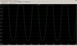
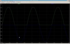
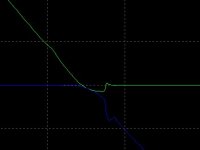
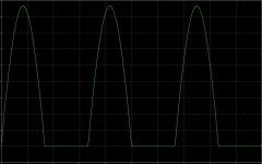
The bias current has a profound effect on switching distortion. If you have a scope, check the waveforms across those emitter resistors while driving a load. This will give you an idea of how good or bad things are. You want to see something like in the picture below. The other one (magnified a bit) show what it looks like when not done right.
The bias current of 1mA is probably a bit on the low side- 10mA or more is better. What the ideal value is depends on a lot of things. To increase the bias current, replace the the 820 ohm resistor in the Vbe multiplier with say a 1k2 and measure again.
The bias current has a profound effect on switching distortion. If you have a scope, check the waveforms across those emitter resistors while driving a load. This will give you an idea of how good or bad things are. You want to see something like in the picture below. The other one (magnified a bit) show what it looks like when not done right.
Attachments
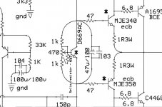
Let me explain the reason for increasing the value of the 820 ohm resistor.
The design equation for a Vbe multiplier is
Vce = Vbe(1 + R1/R2)
R1 is the resistor between C & B and R2 is the resistor between B & E
Now you know where the name comes from. Vbe is multiplied by the factor set with R1 and R2.
Vbe depends on temperature and that's why the transistor must be mounted on the heatsink. In this way the bias is automatically adjusted as the output stage heats up.
In this circuit the voltage Vce is in parallel with the Vbe's of the driver transistors. The collector current of a transistor is a function of Vbe. It should now be clear how the bias current of the output stage is controlled. If I explained it properly, that is.")
Note that if you overdo the bias current, you may end up with a class A amplifier where the output transistors are always on. Your heatsink will probably not be able to cope with this and the magic smoke may make an appearance.
The design equation for a Vbe multiplier is
Vce = Vbe(1 + R1/R2)
R1 is the resistor between C & B and R2 is the resistor between B & E
Now you know where the name comes from. Vbe is multiplied by the factor set with R1 and R2.
Vbe depends on temperature and that's why the transistor must be mounted on the heatsink. In this way the bias is automatically adjusted as the output stage heats up.
In this circuit the voltage Vce is in parallel with the Vbe's of the driver transistors. The collector current of a transistor is a function of Vbe. It should now be clear how the bias current of the output stage is controlled. If I explained it properly, that is.
Note that if you overdo the bias current, you may end up with a class A amplifier where the output transistors are always on. Your heatsink will probably not be able to cope with this and the magic smoke may make an appearance.
Last edited:
The design equation for a Vbe multiplier is
Vce = Vbe(1 + R1/R2)
Hi there Jo' I got it as Vce = Vbe + Vbe*(R1/R2)but the result seems to be the same.
By my calculations if I increase R1 to 1k then the result should be an increase in the Vce of somewhere near 0.2v - Adding this to the 1.2v (the max as it stands)will give me a maximum Vce of around 1.4v
Do you think this is a good place to start?
Firstly, be very careful when altering anything around the vbe multiplier if you are the slightest bit unsure. Maybe use a bulb tester.
Hi there Mool's Its all good so far! I will change the 820 to 1k and wind the pot back to half way again.
Thanks for the tip about the light globe, I am going to look that one up. I think the idea is to use an incandescant globe as a fuse on the transformer - but will do some research before melting anything.
I hope things are going well for you and thanks again for all of your encouragement and wisdom.
For example; I didn't even know that the bias was measured with no input signal. Although it is logical.
- The warning about faulty connections in this region has been noted and the 820r will be replaced with a 1k (oops don't have any 910's), whilst everything is turned off.
- With 1k resistors for both R1 & R2 I will get an increase of about 0.2V in the Vce of the Vbe multiplier, bringing the maximum from 1.2 up to 1.4V.
Attachments
Good to see that it turned out well.
If you have a scope, check the waveforms across those emitter resistors while driving a load. This will give you an idea of how good or bad things are. You want to see something like in the picture below. The other one (magnified a bit) show what it looks like when not done right.
OK. I do have a scope and it gives a good picture, (the x-axis is a little skewed, but not too bad if I tilt my head to one side!) but the problem is that I dont know how to hook it up. I have made an extra probe from some rg## cable and a 10k resistor on the end of the core - it seems to work well on the second channel of the device. So I have two probes. I know how to adjust the time and voltage and can get a picture of the waveforms across both the input and output at the same time.
Any tips?
I mean how do I attach the earth and probe of each lead? To get the picture that you showed me?
No big rush, It's very late and I am going to catch a few ZZZ.
Cheers mate.
The earthing of the scope would mess things up. Hooking up the earth to that part of the circuit would cause a nasty short. You could disconnect the scope earth, but that's never a good idea.
The proper way to do it with a dual-channel scope is to hook the two probe tips up on the two sides of the resistor, invert one channel and then add the two channels together. The earth leads go to earth as usual.
That should give you a trace like below. Unless your scope has four channels, you will only be able to view one half of the picture at a time. It should however give you an idea of what the crossover distortion is.
To answer another question - the relationship between Vbe and Ic is logarithmic. A small change in Vbe can therefore change Ic in a big way. Another thing - the equation for Vce given above is only an approximation. The measured value would probably be different from the one that was calculated.
Here is the equation for the relationship between collector current and base-emitter voltage:
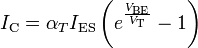
VT is the thermal voltage = kT/q (T is the temperature and VT works out to about 26mV at room temperature) .
Once again, the above is only an approximation. A more accurate equation is:

Don't worry about it. The important part is that Ic depends on Vbe and temperature in a non-linear way.
But if you want to know more, a good place to start is in Wikipedia:
http://en.wikipedia.org/wiki/Bipolar_junction_transistor#Ebers.E2.80.93Moll_model
The proper way to do it with a dual-channel scope is to hook the two probe tips up on the two sides of the resistor, invert one channel and then add the two channels together. The earth leads go to earth as usual.
That should give you a trace like below. Unless your scope has four channels, you will only be able to view one half of the picture at a time. It should however give you an idea of what the crossover distortion is.
To answer another question - the relationship between Vbe and Ic is logarithmic. A small change in Vbe can therefore change Ic in a big way. Another thing - the equation for Vce given above is only an approximation. The measured value would probably be different from the one that was calculated.
Here is the equation for the relationship between collector current and base-emitter voltage:
VT is the thermal voltage = kT/q (T is the temperature and VT works out to about 26mV at room temperature) .
Once again, the above is only an approximation. A more accurate equation is:
Don't worry about it. The important part is that Ic depends on Vbe and temperature in a non-linear way.
But if you want to know more, a good place to start is in Wikipedia:
http://en.wikipedia.org/wiki/Bipolar_junction_transistor#Ebers.E2.80.93Moll_model
Attachments
Last edited:
Yes, the bulb is just a 100 watt mains filament bulb in series with the live supply to the amp.
Once you are sure it's OK then turn the bias current back down and readjust on full mains.
Scope use... to be safe and avoid mishaps you just need ONE earth (probe earth) connection to the zero volt or "ground" line of the amplifier.
Remember if the scope is earthed at the mains and if the amp is earthed at the mains then the scope ground lead (on the probe) will apply a dead short to anything it touches in the amp. Obvious when you think about but easy to forget or accidently let the lead brush over a rail or something.
Here is a scope shot of crossover distortion. This particular design needs the higher bias... yours does not... but it will show the effect. The non linearity is clear to see using a triangular ramp waveform. Shown is input and output on the same screen.
http://www.diyaudio.com/forums/soli...mp-sonic-benefits-approach-3.html#post1569553
- Status
- This old topic is closed. If you want to reopen this topic, contact a moderator using the "Report Post" button.
- Home
- Amplifiers
- Solid State
- Engineer, help please - Neg. feedback/infilters