Actually, the bias current is sensed by resistors and processed by small signal (thus low power) circuits.
The diodes just play a role of end stops, or abutments, to avoid unnecessary waste or heating, they play no active role.
By the way, this circuit has nothing in common with the Krill: the circlophone is completely non-switching, with the OP devices never going off, whereas the Krill uses a hard-switching mechanism upstream of the power devices, and manages it with the help of the speed of the low power devices involved, and minimizing the switching step amplitude by a careful adjustment of the base spreader.
It is easy to highlight by looking at the subtraction residue of the output voltage and a scaled input voltage: the switching action is clearly visible.
My old Hameg scope features a Chan I / Chan II difference mode. That may not be outmost accurate, ( and in fact, cannot) , but anyway, the difference of output and input ( scope attenuators adjusted according to the amp gain) i do not see any kind of crossover distortion with the preliminary Circlo build. This is not so in the case of industrial amp. ( Which is a switching AB).
In LTSpice this difference mode is most easy to implement.
Before continue ( with PCB) i need to know how to give the circlo a "negative output impedance" - by positive feedback, and how to turn it into transconductance amp
In LTSpice this difference mode is most easy to implement.
Before continue ( with PCB) i need to know how to give the circlo a "negative output impedance" - by positive feedback, and how to turn it into transconductance amp
Yeah, I just forgot some stuff from back when I was playing with the Circlophone.
The Krill output stage is a difficult call because I'm still not sure how to bias it right. Even in simulation I'm not sure yet, but it's looking like my praise of it isn't really warranted.
The Krill output stage is a difficult call because I'm still not sure how to bias it right. Even in simulation I'm not sure yet, but it's looking like my praise of it isn't really warranted.
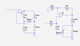
Since the circlophone has the normal, explicit in(+), in(-), out configuration, you can use the usual tricks:Before continue ( with PCB) i need to know how to give the circlo a "negative output impedance" - by positive feedback, and how to turn it into transconductance amp
Two typical examples below, first one varying between Zo=0 and ∞ (transconductance), and second one between Zo=0 and -(any arbitrary value).
By selecting suitable values, the transition can be smooth (inasmuch as the speaker's impedance allows).
With a bit more of noodle twisting, it is possible to combine both circuits, and it is also possible to keep the load grounded, but it is more expensive in terms of component matching and CMMR
Attachments
I'm interested. are there any kits available? also, what is the standing idle power draw in watts? I would like to build it for a 12v DC system, can it operate on such a low voltage?
If there are no kits available, what post contains the parts list?
Would a smaller version be possible, one that can reduce idle power consumption? obviously taking into account reduced power output too, I just need 1 watt RMS.
If there are no kits available, what post contains the parts list?
Would a smaller version be possible, one that can reduce idle power consumption? obviously taking into account reduced power output too, I just need 1 watt RMS.
Last edited:
Since the circlophone has the normal, explicit in(+), in(-), out configuration, you can use the usual tricks:
Two typical examples below, first one varying between Zo=0 and ∞ (transconductance), and second one between Zo=0 and -(any arbitrary value).
By selecting suitable values, the transition can be smooth (inasmuch as the speaker's impedance allows).
With a bit more of noodle twisting, it is possible to combine both circuits, and it is also possible to keep the load grounded, but it is more expensive in terms of component matching and CMMR
Yes thanks. The load need not be grounded in active speaker. I am about to implement Stahl's patent for the woofer. Negative impedance amps should be -naturally, so to speak - unstable especially when driving reactive loads. The simple goal is to compensate the resistance of the voice coil ,thus that a particular woofer fits ( Thiele Small and such) in an alignment even if the box volume is too small.
Ok will try a sim with a Spice woofer model ( first closed then ported box)
Last edited:
None that I am aware of.I'm interested. are there any kits available?
Mickeymoose had made an attempt, but he didn't meet much success, probably because of the format and options chosen, look from here:
http://www.diyaudio.com/forums/solid-state/189599-my-little-cheap-circlophone-37.html#post2828041
The standard quiescent current draw is rather high, typically between 150 and 200mA, irrespective of the supply voltage.also, what is the standing idle power draw in watts? I would like to build it for a 12v DC system, can it operate on such a low voltage?
With a few minor adaptations, operation on 12V is certainly possible, but I am not sure this is the best candidate for such applications.
Under these conditions, the power draw would be ~2W, unless some things are scaled down.
For practical information, start here (it exists in many sizes, flavors, output power, etc):If there are no kits available, what post contains the parts list?
http://www.diyaudio.com/forums/loun...ch-preamplifier-part-ii-5691.html#post4098128
If only 1 or 2W is required, many things can be scaled down: supply voltage, quiescent current, device size etc: it would become a midget or pocket-circloWould a smaller version be possible, one that can reduce idle power consumption? obviously taking into account reduced power output too, I just need 1 watt RMS.
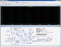
The circlo sim unveiled a problem. I changed the single rail sim to npn with trusted BJT models but the problem remains. To determine output impedance, in practice a sine voltage source is connected to the amp output via a resistor typically 5 to 8 Ohms, the amp input shortened. The sim of such a setup works with several Spice models of amps, showing - as expected- some distortion. But the Circlo sim cannot handle that.
Seems to work well enough for me:
Edit:
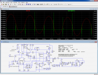
Also works for time domain, but not for the computed impedance trace obviously, because of the indeterminations caused by the 0-Xings
Edit:
Also works for time domain, but not for the computed impedance trace obviously, because of the indeterminations caused by the 0-Xings
Attachments
Last edited:
It also works. It must be an option in the control panel: try changing the solver, etcthe sine gen at output is usually set to amplitude 20 volts
Ok. Looks much like another issue with Spice models..... Alternate solver gives "better" results. Anyway, this test should unveil more about the amp's feedback, compensation etc. than a "forward" test. Some audio magazines and an US audio scholar ( do not recall his name) claim that keeping the OPS out of the global feedback loop reduces so called reactive distortion significantly. Don't know whether this shows up in a Spice sim.
Basically, any servo'ed power system has an inductive behavior at its output, because of the delay in the path, meaning that any perturbation imposed at the output is corrected with some phase shift increasing with frequency, thus mimicking an inductor.Some audio magazines and an US audio scholar ( do not recall his name) claim that keeping the OPS out of the global feedback loop reduces so called reactive distortion significantly.
That is true of amplifiers, voltage regulators, etc and explains why ringing (or even oscillation) appear when the load is a pure capacitance.
The phenomenon is thus real, and quite well-known in fact, but is it a reason to remove the OP stage from the loop, knowing it is generally the dominant source of distortion in an amplifier?
I don't think so, there are better tradeoffs IMHO.
That said, it is possible to correct the OP stage alone using techniques not involving FB: my UniGaBuf is an example of that.
I would like to build it for a 12v DC system, can it operate on such a low voltage?
... / ...
Would a smaller version be possible, one that can reduce idle power consumption? obviously taking into account reduced power output too, I just need 1 watt RMS.
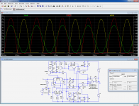
Here is an attempt at a midget Circlophone: CircloBonsaï.
The modifications consist mainly of simplifications: singles as OP, no zener, and a few resistor values adapted.
The Iq has been reduced to 65mA
With 12V total supply (+/-6V), it delivers 10Vpp into 2Ω before clipping, that is 6W average power.
2V total waste is not bad for a general purpose amplifier, but cannot compare with specialized amplifiers for car radio and other low voltage applications having common emitter output.
The OP can be high Hfe types like 2SC1983 or its P counterpart, BD434, etc.
The circuit could also undergo a complete sex-change operation, or operate in a single supply config as shown above: this would give a slight advantage for output power, because the positive side has a little more headroom, and with a proper bias, 10.5~11Vpp output would be possible.
Attachments
but is it a reason to remove the OP stage from the loop, knowing it is generally the dominant source of distortion in an amplifier?
I don't think so, there are better tradeoffs IMHO.
That said, it is possible to correct the OP stage alone using techniques not involving FB: my UniGaBuf is an example of that.
What I know about these topologies is that the PSUs are sort of extravagant...
the UniGaBuf is certainly interesting but I assume not as hand-tame as the Circlophone.
One of these highly venerated amps works with SiC Mosfets. Only n channel possible. I have some reason to assume that it is a sort of UniGaBuf.
These SiC Fets play a huge role in DC DC converters , such as in e- autos. They are said to be very fast switchers, and can operate up to 200 degrees Celsius, thus i believe the audio future will belong to error-forward corrected class D.
Last edited:
Circlophone is well suited for active speakers, where the lack of short and SOAR protection is not an issue. With dual PSU i think the output/speaker relay can be omitted as this topology will not bump at power on. A speaker protection in case of malfunction could be PSU shutdown and shorting the load capacitors via 1 ohm or so.
- Home
- Amplifiers
- Solid State
- ♫♪ My little cheap Circlophone© ♫♪