Excellent!
Taking notes for my cascode output stage, in case I need 2 cascode FETs in parallel.
> The IRFP250 are old devices, and do not have a too steep Id/Vgs curve, but more modern devices would be more demanding
Modern high transconductance FETs would also have more Spirito effect, so they would go poof.
Taking notes for my cascode output stage, in case I need 2 cascode FETs in parallel.
> The IRFP250 are old devices, and do not have a too steep Id/Vgs curve, but more modern devices would be more demanding
Modern high transconductance FETs would also have more Spirito effect, so they would go poof.
> Taking notes for my cascode output stage, in case I need 2 cascode FETs in parallel.
Indeed, and as you already noted in your other threads, the source resistors can be dispensed with without problem: my trials lasted quite some time, and as the global dissipation was substantial, the heatsink became quite hot, but it had no effect on the current sharing.
I just had to reduce the offset of the generator to keep the peak current of the transistors at 6.4A
Maybe adding a low value resistor to the lowest threshold FET would help with current sharing... after all, who cares if they don't share current equally at low power, it only becomes important at the highest current values.
Measuring and adding some resistors is much simpler than matching, and there are no leftover FETs at the end of the process, but will it work?
Measuring and adding some resistors is much simpler than matching, and there are no leftover FETs at the end of the process, but will it work?
I don't think you need to bother with that: a coarse, single point matching (100mV or lower would be sufficient with the IRFP250) on devices from the same batch would be sufficient.
In my test, I deliberately used heterogeneous devices, but with a more homogeneous lot, a basic sorting should be sufficient.
A maniac, extra-accurate matching at low current is not required as it does not completely reflect the high-current behaviour: the test including the ~200mV off device gave better results than the almost ideal triplet.
Of course, when the mismatch reaches 400mV, things begin to turn sour, but that's to be expected, and the impact was not that high, considering: a 50% unbalance.
I would have expected the low-Vto one to carry all the current, with the two others completely off, but a significant sharing remained
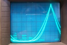
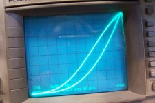
Here it is:

I added a 71mΩ to the 3.31V one (the two others are 3.56 and 3.73V).
It does the job, obviously, but with he peak currents equalized, the region between 0 and 6.4A is significantly altered: it is visible in the much wider "skirt" of the characteristic.
Completely normal, of course, but is it acceptable?
Attachments
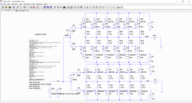
I have explored the Vto dispersion idea in greater details.
I have used sounder models in the sim: IRF530 and IRF9640.
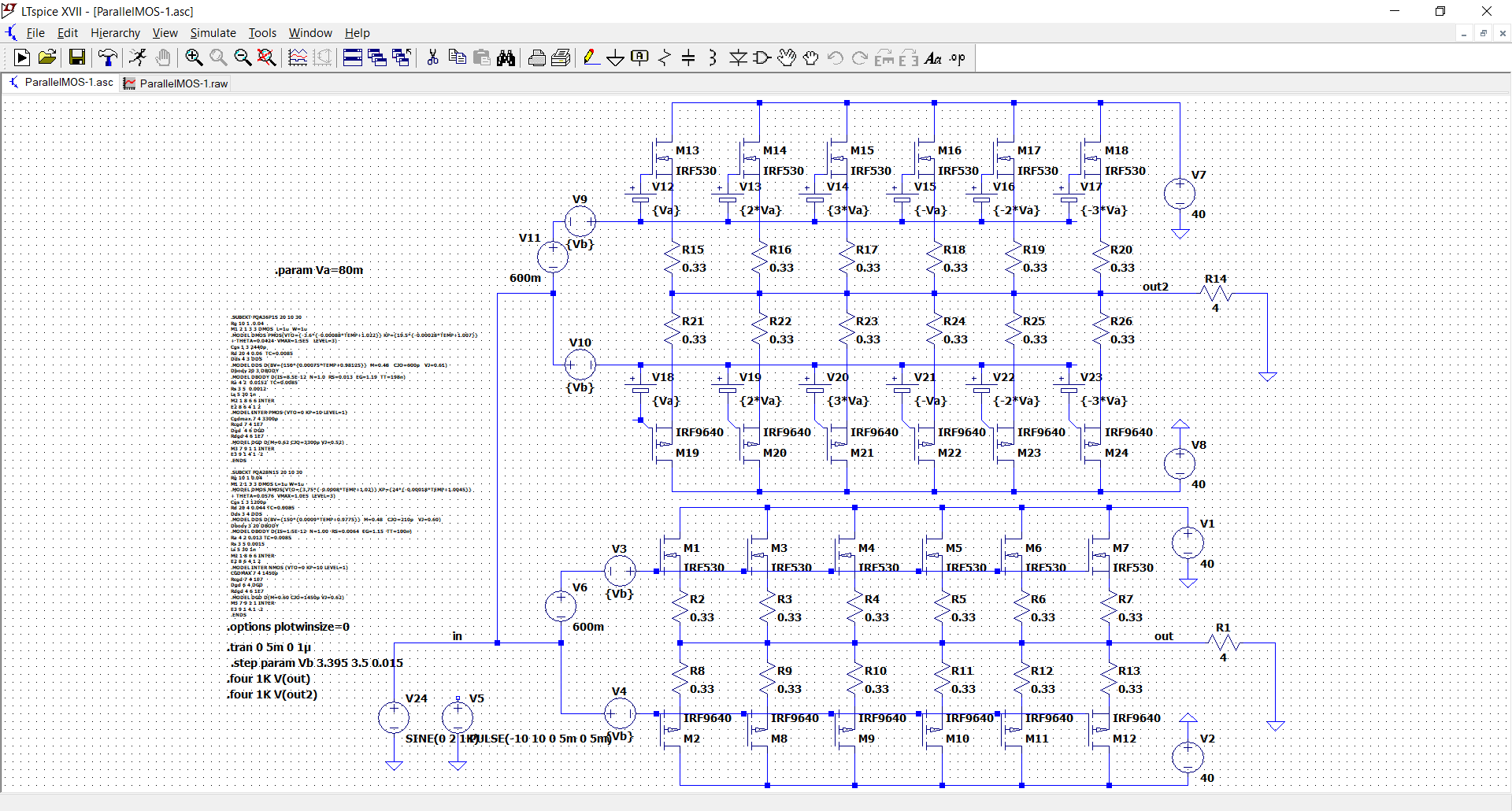
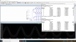
The results on the crossover distortion are quite spectacular: this is the first iteration (lowest bias current)
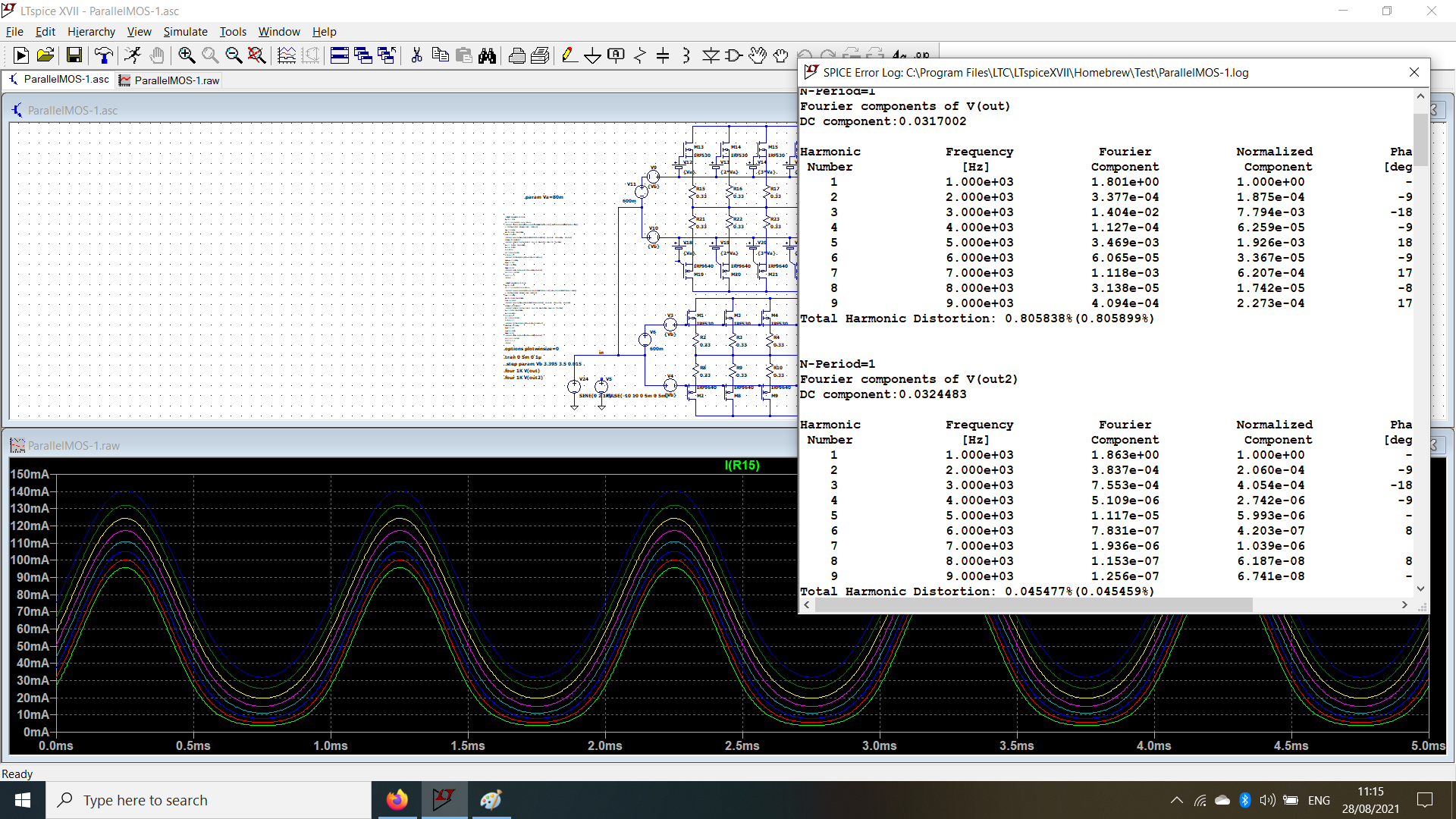
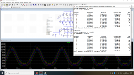
And this is the last one:
Not so spectacular, but still a worthwhile improvement
I have used sounder models in the sim: IRF530 and IRF9640.
The results on the crossover distortion are quite spectacular: this is the first iteration (lowest bias current)
And this is the last one:
Not so spectacular, but still a worthwhile improvement
Attachments
I added a 71mΩ to the 3.31V one (the two others are 3.56 and 3.73V).
It does the job, obviously, but with he peak currents equalized, the region between 0 and 6.4A is significantly altered: it is visible in the much wider "skirt" of the characteristic.
Completely normal, of course, but is it acceptable?
Alright!
You're measuring current across the 25 mOhm resistors for all channels, right?
Since gm = dIs/dVgs and dVgs/dt is constant with a triangle wave, if you trace the derivative directly by adding a C-R filter at the output of the current sense amp, you will get gm... And in fact since only total gm matters, if you sum the voltage across 25mOhm resistors and take the derivative with a cap, you'll get gm of the whole output stage...
It should not make a big difference: if total bias current is the same, and since gm is roughly proportional to current, gm at zero current should be quite close whether you have one FET with low Vth conducting all the bias, or 3 FETs with matched Vth conducting 1/3 of the bias each... the sum should be the same...
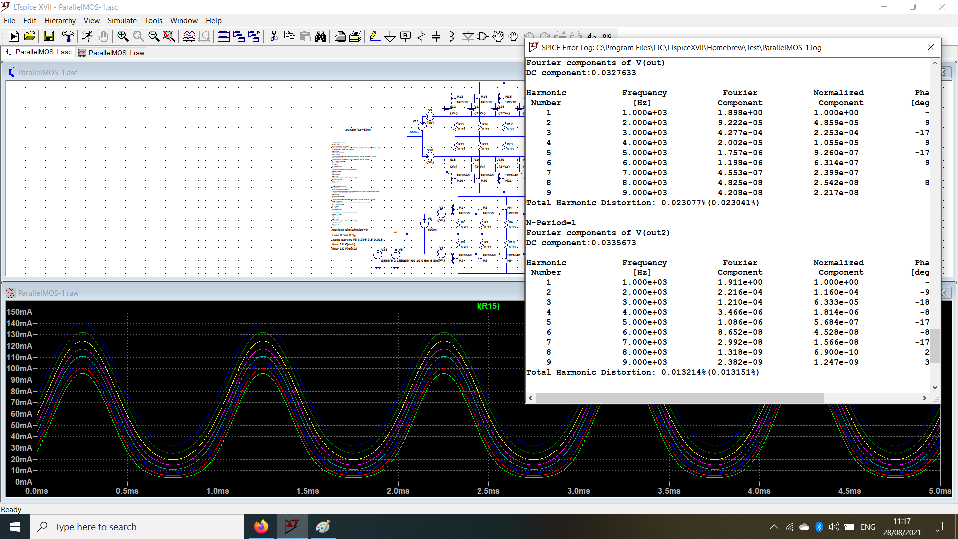
I have explored the Vto dispersion idea in greater details.
I have used sounder models in the sim: IRF530 and IRF9640.
The results on the crossover distortion are quite spectacular: this is the first iteration (lowest bias current)
And this is the last one:
Not so spectacular, but still a worthwhile improvement
Hopefully I'm not wrong to say "not bad!" Small achievements are still achievements.
(And your PM inbox is full.
 )
)All these tests are focusing on sharing current.
From my experience of building mosfet amps with multiple pairs,
the real problem is that even slightly unmatched mosfets are VERY likely to oscillate.
How to fix that? G-D snubbers? Bigger gate stopers?
Beads on gates are mentioned many times, yet I've never seen any practical guides how to use
them. Haven't seen even one amp on this forum actually using them.
Don't know how to select these beads, based on what parameters?
Any advice? Examples?
Last edited:
Mr Minek123,
I have seen one time favourite Elektor Cresendo and Minicresendo Amplifiers, using standard 220R gate resistors. I had read somewhere that the builders of Cresendo amplifier faced oscillation problems as this amplifier uses 2 MOSFET in parallel. Although they used Lateral 2SK and 2SJ series mosfet's from Hitachi which have very low GS threshold voltage. I could not make prototype of these amplifiers as these MOSFET were not easily available in India and were very expensive at that time.
However I had build one prototype of Elektor BUZ23 amplifier about 20 years back with two IRF350 Mosfet in parallel using 100R as Gate resistors and did not face problems of oscillations. The quality of sound was excellent but the only problem I faced was the bias stabilisation. So I did not proceed further for a Stereo setup.
The Ferrite beads as suggested by Mr Elvee seem a viable solution to curb oscillations but is yet to be tested in real life.
> The quality of sound was excellent but the only problem I faced was the bias stabilisation.
This could be caused by mosfets oscillating - voltage drop on source resistors behaving erratically.
The oscillating fet will draw more current than the rest of them.
Or perhaps you had problems with tempco?
This could be caused by mosfets oscillating - voltage drop on source resistors behaving erratically.
The oscillating fet will draw more current than the rest of them.
Or perhaps you had problems with tempco?
“Good decoupling” means a low inductance AC path from the rail to *signal ground*. Keeping the power ground and signal ground separate is needed for lowest distortion, but that can reduce the effectiveness of your bypassing. When you start making physically large banks of mosfets all those ground paths get longer and eventually you develop enough inductance to be a problem. Larger gate stops are just a band aid, and will eventually degrade the non-dominant poles inside the intentional global feedback and eat into phase margin. Small gate stops are all that is needed to prevent parallel FET (odd mode) oscillation.
YesAlright!
You're measuring current across the 25 mOhm resistors for all channels, right?
Here are the results: I first tried to do it digitally, using the math function of the scope, but the dynamic range was not sufficient to get a comfortable full-screen view and I ended up extracting it analogically.Since gm = dIs/dVgs and dVgs/dt is constant with a triangle wave, if you trace the derivative directly by adding a C-R filter at the output of the current sense amp, you will get gm...
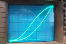
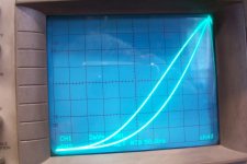
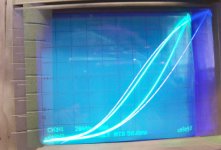
First, a "normal" FET (no resistor, Vto=3.52V)
Next the one with the resistor:
And finally, the global average:
The vertical scale for the derivative is arbitrary and relative: I simply tweaked the parameters to arrive at a full-screen waveform.
The most obvious (and expected) difference is the dilution of the exponential component by the resistor
It is certainly worth investigating; whether it will translate into real, physical improvements remains to be seen: for the moment, it is just a sim, but the "dithering" effect looks like a sensible, useful conceptHopefully I'm not wrong to say "not bad!" Small achievements are still achievements.
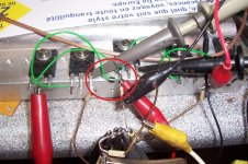
I use them all the time: for example, for this test I had to use two of them (the other one is hidden behind a probe)Beads on gates are mentioned many times, yet I've never seen any practical guides how to use them. Haven't seen even one amp on this forum actually using them.
Mostly trial and error.Don't know how to select these beads, based on what parameters?
Any advice? Examples?
The inductance added must be low enough not form a LP filter having a Fo affecting the loop characteristics of the amplifier, but other than that you have to rely on experimentation.
Sometimes, a // combination of a discrete inductor and resistor works better: you are free to chose the inductance and the damping separately
Sensible advice there, which is why ferrite beads are more effective than resistors, as they target VHF effectively without impacting too much the loop characteristicsLarger gate stops are just a band aid, and will eventually degrade the non-dominant poles inside the intentional global feedback and eat into phase margin. Small gate stops are all that is needed to prevent parallel FET (odd mode) oscillation.
Attachments
>Mostly trial and error.
>The inductance added must be low enough not form a LP filter having a Fo affecting the loop characteristics of the amplifier, but other than that you have to rely on experimentation.
Elvee, so let's say I want to buy a set of several beads from Mouser, for experimentation.
Can you point me to a few actual samples of what should I buy?
A range of inductances for example?
“Good decoupling” means a low inductance AC path from the rail to *signal ground*.
There is no such thing as "signal ground".
https://www.edn.com/the-g-word-how-to-get-your-audio-off-the-ground/
Last edited:
Elvee, so let's say I want to buy a set of several beads from Mouser, for experimentation.
Can you point me to a few actual samples of what should I buy?
A range of inductances for example?
When I used inductive resistors on the "output stage measurement" topic, some transistors oscillated. I used some B-20F-46 on the gate/base pin and that worked well. TO-264 pin fits in the hole. There are several models, shorter and longer, with corresponding impedance (type B-20F- in the search box).
Now "how to choose them" is a bit like seasoning, you put them in to compensate for circuit parasitics that are unknown, so it's trial and error. These beads are lossy on purpose, so they're like crap low Q inductors, and the loss dampens oscillations. It's an inductor, but the inductance is not really wanted, it's just a side effect. At high frequency the losses dominates so it becomes a resistor. So quite often L is not specified and you have to check the spice model to make sure it doesn't resonate at low frequency with the caps in your power supply filter.
If you look at the impedance graph it shows "X" which is reactive impedance from the inductance, and "R" which is resistive impedance from the lossy core. You want low L (because that gives extra phase shift in your loop gain) and high R to dampen oscillations. Those that fit tend to have "not too high" Z at 100MHz like 100 ohms or below, and definitely low Z below 10MHz or you get a free extra pole in your amp.
The same stuff is available from different manufacturers at various prices, Reichelt has cheaper versions, as usual. The datasheet gives impedance curves.
The beads are convenient for experimenting. They are slightly conductive and thick enough to short base to collector if used on a TO-220, but a bit of tape fixes that. You can also use SMD ferrite beads (they are beads in name only, there's no hole, it's a multilayer construction) but that's not very user-friendly for prototyping with wires... and the nice thing with the physical beads (cores with a hole) is they don't need labels ; longer = higher impedance, and if you put several on a wire, it increases the impedance like if they were in series.
Last edited:
- Home
- Amplifiers
- Solid State
- ♫♪ My little cheap Circlophone© ♫♪