A good starting point for AF work is 500nH to 1µH, material MnZn. Often, the inductance is not specified, but the impedance/vs frequency always is, and it's easy to get back to the inductance from lowest graph frequency, where losses do not influence the impedance.Elvee, so let's say I want to buy a set of several beads from Mouser, for experimentation.
Can you point me to a few actual samples of what should I buy?
A range of inductances for example?
In the example provided by Peufeu, the impedance @1MHz is ~20 ohm.
20/6.28 is 3.3µH, certainly effective, but maybe already excessive in some instances
Something worth noting: in principle, an emitter or source inductor is much more effective than a base or gate one, but it can be too effective or cause other types of unstability, which is why the gentler approach is generally preferable.When I used inductive resistors on the "output stage measurement" topic, some transistors oscillated.
Inductance in the E or S really is the nuclear option. In HF, low power circuits, the E or S is generally favoured because the impedance levels are much higher, and to be effective a B or G inductor would need to be unrealistically high.
It is important to note that the R of the complex graph is different from the impedance magnitude: in the B20F-46 datasheet, only the magnitude is published.If you look at the impedance graph it shows "X" which is reactive impedance from the inductance, and "R" which is resistive impedance from the lossy core.
You can have an idea of the damping by looking at the flattening of the impedance above a certain frequency: an ideal inductor would rise indefinitely.
I think it's normal, for two reasons: remember that in fact three FETs are paralleled. Two do not have a source resistor, and being majority, they dominate by 2 to 1.I put the three scope shots on top of each other. The average looks identical to the single FET without resistor... I guess it dominates. I put the one with the resistor in red.
I'm not sure how to interpret this...
Even in a match between two transistors, the non-resistored one would still dominate, because the resistor value is chosen for an equal sharing at an arbitrary, high current (in this case 6.4A), but the resistor value is probably much larger than the 1/gm increase caused by the correlation to the higher Vto in the non-resistored one.
The problem is that you cannot properly compensate a mostly-offset problem by a mostly-slope correction. The correction is exact for one point (at 6.4A here), but is above or below target
Edit: if you want to retain the characteristics of a resistor-less MOS, but need additional, maybe resistored devices for power/current sharing reasons, you just need a single, "governor" resistor-less MOS. All the others will simply act as slave, or helpers. I imagine that if you push the boat too far, it will cease to work, but with one or two slave devices, it should work.
I can make the test with the two low Vto devices in my setup against the "strong", but high Vto one
Last edited:
To make the next test, I have sorted IRFP250's to find another low Vto sample, to be able to make the 2 + 1 test.
The one I used has 3.36V.
Thus, the lineup for this test is:
3.79V + 0Ω
3.31V + 71mΩ
3.36V + 54mΩ
First, the three Id/Vgs curves together:
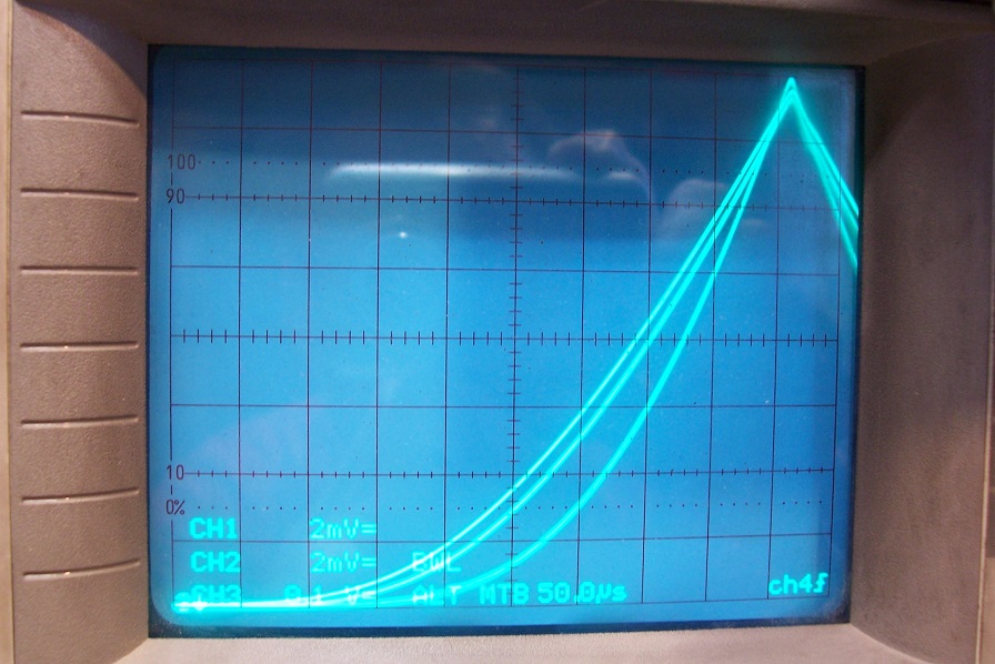
The upper curve is the 3.31V, the middle one the 3.36V and the lowest the 3.79V
Next, the global average and the 71mΩ:
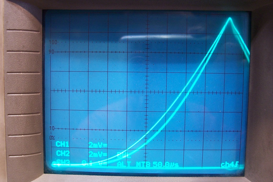
And finally, the global average and 0Ω:

This means that a single, resistor-less device cannot completely dominate two resistor-fitted devices (with the resistor values used here).
It can dominate another single device, but the resulting curve always includes a minor component from the degenerated device.
Another remark about ferrite beads: manufacturers often provide a spice model, and LTspice even has a dedicated library, but the models are very crude: they typically include lumped components, like inductance, series and parallel resistance, but the reality is very different: the actual parameters depend on frequency, excitation, and many higher effects like magnetoresonance, complex permeability, magnetic hysteresis, etc. are not modeled.
Including them in a sim is better than not, but the reality can be seriously different, which is why experimentation remains essential
The one I used has 3.36V.
Thus, the lineup for this test is:
3.79V + 0Ω
3.31V + 71mΩ
3.36V + 54mΩ
First, the three Id/Vgs curves together:
The upper curve is the 3.31V, the middle one the 3.36V and the lowest the 3.79V
Next, the global average and the 71mΩ:
And finally, the global average and 0Ω:
This means that a single, resistor-less device cannot completely dominate two resistor-fitted devices (with the resistor values used here).
It can dominate another single device, but the resulting curve always includes a minor component from the degenerated device.
Another remark about ferrite beads: manufacturers often provide a spice model, and LTspice even has a dedicated library, but the models are very crude: they typically include lumped components, like inductance, series and parallel resistance, but the reality is very different: the actual parameters depend on frequency, excitation, and many higher effects like magnetoresonance, complex permeability, magnetic hysteresis, etc. are not modeled.
Including them in a sim is better than not, but the reality can be seriously different, which is why experimentation remains essential
Attachments

Last edited:
> This means that a single, resistor-less device cannot completely dominate two resistor-fitted devices (with the resistor values used here).
Cool, so someone too lazy to match MOSFETs could still get reasonable current sharing by playing with resistors...
Murata gives all their ferrite bead spice models on their "simsurfing" website, but sadly these do not model saturation due to current. So they're not that useful for power supply filtering.
Do you think hysteresis from a ferrite bead would add distortion?
> Do you think hysteresis from a ferrite bead would add distortion?
Let's make the calculation for the example you gave:
The outer diameter is 4.6mm, inner 1.5mm and length 4.3mm. The geometric core area is thus 4.3*(4.6-1.5)/2 = 6.66mm²; the effective area would be slightly different, but we do not need to worry about that: a square-section toroid is almost a canonical shape, and the section is completely uniform.
We need the specific inductance, which was derived earlier from the impedance: 3.3µH.
The maximum tolerable current for a given induction B is I=n*B*A/L.
Here, by definition the number of turns n is 1, thus for an induction of 0.3T, which begins to be highish for a signal, MnZn ferrite, I=0.3*6.66/3.3=0.99A.
This is the maximum, instantaneous peak current value.
If you use the bead in the gate connection, it probably doesn't matter.
If you use it in the source, it will already begin to have an impact at moderate power levels.
What impact?
When the current exceeds 0.99A, the inductance (and thus the reactance at the frequency of interest) will begin to fall, until it collapses completely when the current causes an induction of ~450mT.
The non-linear degeneration will probably have a negligible effect at frequencies <100Hz, but at 20kHz, it will have the effect of switching on and off a degeneration of ~0.41ohm during the cycle, and this will have a major impact on the THD.
To be really free from pre-saturation effects in a MnZn ferrite, it would be safer to keep the induction below 200mT.
NiZn ferrites have more non-linearities and a lower saturation value, but they have a much lower µr, meaning that you are unlikely to reach saturation with a bead of similar value, because it will require a much larger Ae to reach that specific inductance.
However, at HF, where the suppression effect matters, they will have a larger Q, lower damping, making them less suitable for AF use, where local oscillations rarely fall outside a ~15-150Mhz range
I messed up my arithmetics: I= 0.604A.I=0.3*6.66/3.3=0.99A.
Does not change a lot, and it's just an example anyway.
Most of the Elektor circuits used parallel combination of 1R non inductive carbon resistors in Source of MOSFET instead of equivalent value of single high power wire wound resistor.
I got good results with the modern equivalent which is a parallel combo of 1R 1W SMD resistors.
In the emitter that would increase distortion a lot...
But I was thinking about hysteresis, not saturation
Ooops!
I studied the subject in this thread:
Non-linearities of cored inductors
For example, at ~40mT, a 3H1 ferrite (an ordinary MnZn material) has a root non-linearity of 0.45%.
This means that at 20kHz, the 0.41ohm reactance will be affected by the same factor.
Whether it has an impact on the THD of the amplifier or not depends on a lot of factors, all specifically related to the exact circuit
OK so 0.45% of 0.41ohm reactance is 1.8 mOhm nonlinear impedance in series with the base ; dividing by hFe of ~100 gives the equivalent if it was in series with the emitter, so that's 18 µOhm or 2ppm of the 8R load impedance...
Nice to have numbers that show it's pretty safe to ignore it
Nice to have numbers that show it's pretty safe to ignore it
Hysteresis has another, more desirable feature: it is a loss mechanism, and therefore contributes to the damping effect.
It only has a very small impact on the lumped components used in basic models, meaning the real world damping effect will generally tend to be higher than what the sim predicts
It only has a very small impact on the lumped components used in basic models, meaning the real world damping effect will generally tend to be higher than what the sim predicts
Elvee, can we short-circuit each board's/channel's drain/collector pins together? Or, can we use single schottky diode and 1R,0.5R resistors for each rail then distribute the rails to drain/collector pins at this point?
I'm asking this because possibility of using two different heatsinks for each rail without using any isolation pads in order to minimize thermal resistance with TO220 devices.
I'm asking this because possibility of using two different heatsinks for each rail without using any isolation pads in order to minimize thermal resistance with TO220 devices.
Keratherm Red silpad has the same thermal performance as grease, with isolation, but it is more expensive.
OK!
Hysteresis has another, more desirable feature: it is a loss mechanism, and therefore contributes to the damping effect.
It only has a very small impact on the lumped components used in basic models, meaning the real world damping effect will generally tend to be higher than what the sim predicts
OK!
All interface materials have a finite thermal resistance, and keratherm is no exception.
When the surface condition of the heatsink is imperfect, an interface material compliant enough to adapt itself to a rough surface may appear to equal a direct contact with an ordinary thermal compound (typically silicone grease with ZnO as a filler), but with properly polished surfaces helped by a good thermal compound (silver-based for example), the direct contact is always superior.
Keratherm's have a good thermal performance, but they come nowhere near copper, silver or aluminum regarding thermal conductivity.
When the heatsink has a thick anodized layer of aluminum oxide, its thermal resistance can be high enough compared to the pad, rendering any difference negligible.
The main advantage of pads is their ease of use: they give good performance without requiring maniac care, and they avoid the mess of a semi-liquid compound
Of course
But it's really convenient, you get isolation, good thermal performance, and no mess.
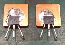
For parts that have a tiny package, interface with the heat sink really matters. There's gallium based materials but they destroy aluminium. So for DIY use, rather than polishing the surface flat which is hard to do without a milling machine, I'd just use solder and a copper slug, but so far I haven't found ones that are both cheap and flat enough. The ones pictured below are definitely cheap, but not really flat. It's okay for these devices though, they work anyway due to just having a lot of surface area.
But it's really convenient, you get isolation, good thermal performance, and no mess.
For parts that have a tiny package, interface with the heat sink really matters. There's gallium based materials but they destroy aluminium. So for DIY use, rather than polishing the surface flat which is hard to do without a milling machine, I'd just use solder and a copper slug, but so far I haven't found ones that are both cheap and flat enough. The ones pictured below are definitely cheap, but not really flat. It's okay for these devices though, they work anyway due to just having a lot of surface area.
Attachments
I used "Arctic Silver® 5", High-Density Polysynthetic Silver Thermal Compound between my PC CPU and its Heat sink. This gave me excellent results.
Arctic Silver 5 is conductive. Need to use a mica with that, and be careful that it doesn’t bleed to the screw threads when mounting power transistors. It is an order of magnitude better than the white goop. It’s really good if you can direct mount to the heat sink (grounded collectors, or live heat sinks).
Of course
For parts that have a tiny package, interface with the heat sink really matters. There's gallium based materials but they destroy aluminium. So for DIY use, rather than polishing the surface flat which is hard to do without a milling machine, I'd just use solder and a copper slug, but so far I haven't found ones that are both cheap and flat enough. The ones pictured below are definitely cheap, but not really flat. It's okay for these devices though, they work anyway due to just having a lot of surface area.
That little trick is the ticket for making your own TO126 or TO220 devices out of surface mount devices. Soldered interface to the device is as good as it gets. Then you just have to worry about the interface from the slug to the bigger heat sink. The poorer the flatness, the bigger it needs to be. If you have room for something the size of. a TO264 you can make it work. Room to drill mounting holes, and understand that it *will* potato-chip a bit when you torque it down leaving the worst gap right under the die. Putting a bar clamp across two might be preferable.
- Home
- Amplifiers
- Solid State
- ♫♪ My little cheap Circlophone© ♫♪