Having thought it through, I can see that common mode chokes will have a potentially role once I connect a mains ground to my audio ground. When I do that I will do some testing to see what differences I can hear.
But I cannot see how a common mode chokes could ever replace the function differential chokes. Perhaps having both would be ideal but for now my differential filters are doing just fine on their own")
But I cannot see how a common mode chokes could ever replace the function differential chokes. Perhaps having both would be ideal but for now my differential filters are doing just fine on their own
Aren't common mode and differential mode chokes the same?
http://www.coilcraft.com/pdfs/comoco.pdf
I already said the common-mode choke isn't to prevent ground noise. it is to filter common-mode noise, but it not common mode noise from ground; it is from the rectifiers and mains.
- keantoken
http://www.coilcraft.com/pdfs/comoco.pdf
I already said the common-mode choke isn't to prevent ground noise. it is to filter common-mode noise, but it not common mode noise from ground; it is from the rectifiers and mains.
- keantoken
The hardware could be the same except that the differential version has to be larger to be able to deal with a permanent DC magnetic flux which the common mode does not have to deal with because it has one coil reversed and therefore the applied DC fluxes cancel.
Common mode noise has to be with reference to something and that something is usually going to be ground. So they deal with common mode noise with reference to ground. If there is no reference point the common mode noise will never be able to express itself and will to all intents and purposes be invisible
But actually, whether we call it ground noise or noise with reference to ground is to some extent semantics because in reality it amounts to the same thing.
re post1739 NfetZilla V1.2
This has a bootstrapped CCS as the VAS load.
The clipping performance is different from the plain bootstrapped R for VAS load.
The negative clips early and stays slean and flat topped no matter how high the overload signal gets. This is the same as the bootstrap R v1.1
The positive peak clips at a much higher voltage, (as before). All levels of clip show sticking and then sudden return to sinewave. There is a tiny ripple as it catches up with the sinewave.
The bootstrap R v1.1 slows clean recovery from +ve and -ve clipping.
Well, I fixed my sound. Glad that's over with.
Not to intrude or advertise, but I think this is appropriate in light of recent comments.
SWF, here is the version of my amp that is built right now. It has the sophistication and liveliness... The treble is incredible. The illusion is so great that it is as if you can focus and listen through the background noise. Instruments are very clearly separated, and don't overwhelm each other. It is just like real life, where you hear as much as you want to hear, and not more. But if you pay attention there is a lot that you can hear...
It's just barely adequate for my speakers, and has some flaws, so I will build a revised prototype in the indefinite future. In this amp there are no large capacitive currents, except perhaps in the compensation RC, so I think layout may be a little more forgiving.
If you are curious, I encourage you to try this amp out to compare with Fetzilla, more as a academic excercise, because it has it's flaws. That is what I will be doing anyways.
- keantoken
Attachments
Last edited:
Thanks Kean, looks interesting!
I would not write off fetzilla's treble performance until you have tried it with the recommended devices. You might be surprised.
BTW, I see you suggest a square wave test into 3nF. 3nF has absolutely no effect on fetzilla, even with no compensation. I really only begin to see an effect around 20-30nF.
Andrew,
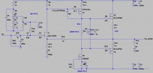
Have you tried a simple self biased depletion mode mosfet or jfet for the CCS? I prefer it this way, and I think it clips a little more cleanly. Unfortunately it is only suitable for relatively low voltage rails though. Here is my current preferred schematic for use with +/- 25v rails.
I would not write off fetzilla's treble performance until you have tried it with the recommended devices. You might be surprised.
BTW, I see you suggest a square wave test into 3nF. 3nF has absolutely no effect on fetzilla, even with no compensation. I really only begin to see an effect around 20-30nF.
Andrew,
Have you tried a simple self biased depletion mode mosfet or jfet for the CCS? I prefer it this way, and I think it clips a little more cleanly. Unfortunately it is only suitable for relatively low voltage rails though. Here is my current preferred schematic for use with +/- 25v rails.
Attachments
Last edited:
I suggest 3nF for my amp because that's the "magic value" of capacitor that's most likely to destabilize it. Fetzilla may have it's own value. One way to know for sure is to plot the output impedance and phase of Fetzilla and make sure it does not go over 90 degrees, but you need the right RF equipment to at least say 50MHz. Is Fetzilla unstable without the output snubber?
It would not surprise me to find Fetzilla has better sound, since I don't know what to expect anyway (I try to avoid anticipation). I am looking forward to testing the new VAS.
I looked at the VPN3310, it looks like a very linear device at high medium currents. In the simulator it has very little distortion. Unfortunately I didn't have the brains to get it.
- keantoken
bf244b is an Nchannel jFET. It works well as a CCS.Andrew,
Have you tried a simple self biased depletion mode mosfet or jfet for the CCS? I prefer it this way, and I think it clips a little more cleanly. Unfortunately it is only suitable for relatively low voltage rails though..
These first two amps were all built from stock items. (that's why some of my caps are unusually large).
I have zvnG and zvnG and 2530 on order. Mouser is not expecting delivery of zvpG until late Sept. I can wait. I don't expect the G or the 2530 to make any noticeable difference to the SQ. But, I might be wrong.
Thanks Kean, looks interesting!
............... Here is my current preferred schematic for use with +/- 25v rails.
OK ! What value is zener D2??
Well, I have the new VAS in and it sounds much better. I had to use 18p miller compensation. The treble is much cleaner and seems to be more musical, although I think it still doesn't provide the same illusion as my amp. In all other ways I think it is better.
I will play with it more, for instance changing gate stoppers or degeneration. However to make progress I may have to improve my speakers somehow.
- keantoken
I will play with it more, for instance changing gate stoppers or degeneration. However to make progress I may have to improve my speakers somehow.
- keantoken
Sandy,
The zener is a current limit on the output stage as Greg found that such zeners between gate and source affected the sound adversely. We carefully examined the failure modes of both outputs and concluded that the only situation where Z2 across the bias generator would NOT protect the output gates was when one or more outputs had fused anyway.... so it seemed logical to assume that a 4V7 zener in this position would do the job nicely as we found it did NOT affect the sound adversely.
If the transconductance of the outputs is nominally 1S (1A per Volt) then a 4V7 zener would limit the quiescent to about 2.5A, which sets the upper bias limit as well as offering gate protection. In normal operation, quiescent set to 1A or lower, of course the zener is not energised at all.
Cheers,
Hugh
Hi Sandy,
Edit: this post is now redundant as Hugh has answered your question.
To be honest I am currently not actually using D2 and D3. They are there to theoretically keep things under control in the event of the trimmers going open circuit. They seem like a good idea though I have never tried them. It's up to you whether you think the diodes are necessary and whether you want to trust the trimmers or other devices not to ever fail.
I would think 4.7v would be a good choice should you go that way.
Cheers,
Greg.
Last edited:
Oh, one more thing Kean.
I think, seeing as though you are chasing realism and perhaps a more sophisticated sound, some phase lead compensation would be good for you. For me, with my terribly bland sounding speakers, the phase lead removed too much life, but it may be just the ticket for your tastes.
I think, seeing as though you are chasing realism and perhaps a more sophisticated sound, some phase lead compensation would be good for you. For me, with my terribly bland sounding speakers, the phase lead removed too much life, but it may be just the ticket for your tastes.
SWF, I propose a trade. I'll take a square wave shot, along with an output impedance square wave test, if you'll do that too.
To test the output impedance, you need to connect the square source directly to the output of the amp, and it must have a series resistor. My scope calibrator has a 10R series resistor, but something like 600R is better; you want it to be more like a current source. I think this test is more useful as to the stability of an amp.
Unfortunately, my scope calibrator doesn't have a fast risetime (1uS+500nS-), so it may not be adequate. I don't know when I might be able to fix my signal generator. If you do this, be sure to note the risetime of your source.
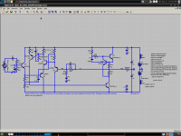
I've attached the schematic for the version that's built and running. Next I plan to lower the gate stoppers to 150N/100P.
- keantoken
To test the output impedance, you need to connect the square source directly to the output of the amp, and it must have a series resistor. My scope calibrator has a 10R series resistor, but something like 600R is better; you want it to be more like a current source. I think this test is more useful as to the stability of an amp.
Unfortunately, my scope calibrator doesn't have a fast risetime (1uS+500nS-), so it may not be adequate. I don't know when I might be able to fix my signal generator. If you do this, be sure to note the risetime of your source.
I've attached the schematic for the version that's built and running. Next I plan to lower the gate stoppers to 150N/100P.
- keantoken
- Status
- This old topic is closed. If you want to reopen this topic, contact a moderator using the "Report Post" button.
- Home
- Amplifiers
- Solid State
- JFET input, MOSFET VAS, LATERAL output = Perfect!!