Standard output inductors are damped with parallel 5-12 ohms and do kill ringing with capacitive loads. That is the principal reason they are fitted.
In my experience this is not the case, rather they just de-couple the amp from the load and only partially damp the ringing
Standard output inductors are damped with parallel 5-12 ohms and do kill ringing with capacitive loads. That is the principal reason they are fitted.
The other reason, according to Hitachi application note, is that: "The output coupling coil has the effect of reducing distortion in the high frequency range"
According to Nationals application note AN-1645:
The Snubber circuit is composed of RSN and CSN. The common value of 0.1μF is chosen for CSN and then a starting value of 10Ω is used for RSN. The pole location created by the circuit is found using Equation: f-3dB = 1/(2πRSNCSN) (Hz)
If small, high frequency oscillation is observed on the output then the snubber values need to be adjusted. Leave the value of RSN set to 10Ω and increase the value of CSN until the oscillation ceases.
Hope this helps.
Quite so and the recently posted Silicon Chip ULD III amp, with 10uH coil is a good example where the higher inductance is used to get better THD performance at >10kHz.The other reason, according to Hitachi application note, is that: "The output coupling coil has the effect of reducing distortion in the high frequency range"
Off topic again but you need only look at current minimalist values of output coils as a reason for poor damping of ringing. Still, some may like that instability.
")
BJT Cascode version
20kHz into 7R + 150nF...
33pF miller cap as only compensation.
Listening test tomorrow...it's 2:40AM!
Looking very promising. This is with BC550Cs in the vas at only 5mA.
Resistive load does a perfect symmetrical square wave.
20kHz into 7R + 150nF...
33pF miller cap as only compensation.
Listening test tomorrow...it's 2:40AM!
Looking very promising. This is with BC550Cs in the vas at only 5mA.
Resistive load does a perfect symmetrical square wave.
Attachments
Last edited:
Hey SWF, did you forget something in all the excitement?
My fetzilla seems to sound the best with plenty of compensation. This makes it sound less lively, but the background is deeper and treble less harsh. I suspect this is an issue with low-level oscillation difficult to detect; without compensation the sound is livelier but the treble seems slightly garbled and the background is not as deep. I wonder if it's possible to find a different way to quell these oscillations.
I think I will have to break down my bench to try and fix my signal generator today.
- keantoken
Maybe the amps is to fast, compensation is most slowdown the amp, and less overshoot and so music get relaxter, also the speaker and filter are complicated load, and there will also things happen special with feedback what woks perfect with only pure ohmic loading, we need a pure ohm load, but this speakers do not excist, maybe only a fostex with fasefilter can maybe sound good on your amp, use a good spectrum analyzer (exspensive) to find difficult detectable oscillations..
Output Choke
Hi All,
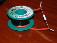
Well I decided to have a go at an output choke again.
I have tried the usual combination of 10 turns of about pencil diameter in parallel with a 10R resistor before with no luck.
This time I thought I would go big, just to see if it could be tamed. So I went stupidly big. I wound about 4 feet of wire on an empty solder bobbin and put that in parallel with a 2W 10R resistor.
Well it worked, and very well too!
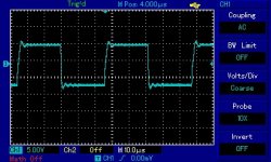
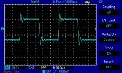
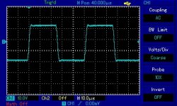
Figures below are the choke, and before and after shots into a 100n capacitive load. Haven't had a listen yet, but fingers crossed!
Looks like I probably should up the vas current slightly and/or use smaller gate stoppers too, that slew rate is not amazing. However the highly asymmetrical drive caused by low vas currents adds nice H2 and I like the sound!
Thanks all for the suggestion. Let's just hope it sounds good too!
Hi All,
Well I decided to have a go at an output choke again.
I have tried the usual combination of 10 turns of about pencil diameter in parallel with a 10R resistor before with no luck.
This time I thought I would go big, just to see if it could be tamed. So I went stupidly big. I wound about 4 feet of wire on an empty solder bobbin and put that in parallel with a 2W 10R resistor.
Well it worked, and very well too!
Figures below are the choke, and before and after shots into a 100n capacitive load. Haven't had a listen yet, but fingers crossed!
Looks like I probably should up the vas current slightly and/or use smaller gate stoppers too, that slew rate is not amazing. However the highly asymmetrical drive caused by low vas currents adds nice H2 and I like the sound!
Thanks all for the suggestion. Let's just hope it sounds good too!
Attachments
Hmm, fascinating, this is with resistive + 100nF, not speaker, load?
Slew rate looks OK; let's see, 30V swing in 2.5uS? That's 12V/uS, which is quite adequate for a 25W amp.
Next question, SWF, did the choke remove the 'zingy' sound?
That is, does it now sound dead, and lifeless, or is it perhaps a "laid back late night with malt whisky" presentation?
Cheers,
Hugh
Slew rate looks OK; let's see, 30V swing in 2.5uS? That's 12V/uS, which is quite adequate for a 25W amp.
Next question, SWF, did the choke remove the 'zingy' sound?
That is, does it now sound dead, and lifeless, or is it perhaps a "laid back late night with malt whisky" presentation?
Cheers,
Hugh
Last edited:
Hi Mike and Hugh,
Unfortunately I did not think to measure it on the amplifier side. These traces are from directly across the load - 7.6R and 100nF. Is the amplifier side likely to be different? I hope not, but will test tonight.
I haven't had a listen yet but I have high hopes for "relaxed and easy going" over "dull and lifeless".
I can't get over how well behaved it is!
With my news PCBs I have dropped the output gate stoppers to 100R which has improved the slew rate slightly.
Fingers crossed this sounds nice!
Here's a wild idea, and something I've never heard of.
Let's assume the choke sounds nice and is "easy going and relaxed". We also know the amp works ok without it and sounds nice and lively.
Since chokes can be exernal to the board, why not have a "mode switch" on the front/back of the amplifier that lets you switch the choke in/out of the circuit and select the operating mode based on the music and listening requirements?
Hi All,
Just thinking and rambling out loud here so bear with me.
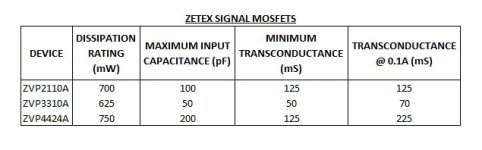
I am trying to find the best device to use in the VAS and have compiled a small table comparing the devices we are using.
I have obtained all the figures from the datasheet tables except the transconductance at 0.1A, which I estimated from the graphs.
It is important to note that the rated transconducance is always at currents far higher than we are using. This is why I have included the transconductance at 0.1A, which is the lowest you can read off the graphs for all three devices. While still 10x higher current than we are using, hopefully it still gives some idea of the relative transconductance at the currents we are talking about.
In this regard the ZVP4424 is the clear winner, assuming more transconductance is better. Though more transconducance may mean less stability.
However I get very nice results from the humble old ZVP3310A with its measly 70mS.
I can also note that the ZVP2110 sounds nice too. It is also available in the G surface mount version which has a 2-3W dissipation - good for more power.
Mike has had good results from the ZVP4424 - high transconductance, high input capacitance. It has a good dissipation rating too.
Both of these have a much higher input capacitance than the ZVP3310A. I wonder what the effect of this is. It may add stability but be more difficult for the JFET to drive.
So, it's interesting to think about the trade offs between input capacitance and transconductance, and which one is more crucial to making this amplifier sound good. Is there a best device, or are all three better in their own way? Will one device sound the best to all of us? Can some be used with no compensation while others can't? Will one that has extra transconductance provide more interstage gain that can then be used for phase lead compensation with less ill effect?
Why do the zetex fets sound so much better than the IRF devices?
Wow, so many possibilities and different circuit incarnations to try and think about.
Anyway, I am going to order all three and try them all in circuit.
Just thinking and rambling out loud here so bear with me.
I am trying to find the best device to use in the VAS and have compiled a small table comparing the devices we are using.
I have obtained all the figures from the datasheet tables except the transconductance at 0.1A, which I estimated from the graphs.
It is important to note that the rated transconducance is always at currents far higher than we are using. This is why I have included the transconductance at 0.1A, which is the lowest you can read off the graphs for all three devices. While still 10x higher current than we are using, hopefully it still gives some idea of the relative transconductance at the currents we are talking about.
In this regard the ZVP4424 is the clear winner, assuming more transconductance is better. Though more transconducance may mean less stability.
However I get very nice results from the humble old ZVP3310A with its measly 70mS.
I can also note that the ZVP2110 sounds nice too. It is also available in the G surface mount version which has a 2-3W dissipation - good for more power.
Mike has had good results from the ZVP4424 - high transconductance, high input capacitance. It has a good dissipation rating too.
Both of these have a much higher input capacitance than the ZVP3310A. I wonder what the effect of this is. It may add stability but be more difficult for the JFET to drive.
So, it's interesting to think about the trade offs between input capacitance and transconductance, and which one is more crucial to making this amplifier sound good. Is there a best device, or are all three better in their own way? Will one device sound the best to all of us? Can some be used with no compensation while others can't? Will one that has extra transconductance provide more interstage gain that can then be used for phase lead compensation with less ill effect?
Why do the zetex fets sound so much better than the IRF devices?
Wow, so many possibilities and different circuit incarnations to try and think about.
Anyway, I am going to order all three and try them all in circuit.
Attachments
Good to see Thiele was correct.Well it worked, and very well too!
- Status
- This old topic is closed. If you want to reopen this topic, contact a moderator using the "Report Post" button.
- Home
- Amplifiers
- Solid State
- JFET input, MOSFET VAS, LATERAL output = Perfect!!