Actualy the maths is right providing we are talking of a single channel...
The upper side of the push pull will suplly the 5.6A half of the time ,
during positive going of the signal while the bottom side will conduct
only on negative cycles of the signal , hence the power supply rails
will be sollicited alternatively, the average current drained by the amp
on each rail will be 2,3A.
On a class AB/B biaised push pull each side conduct only 50% of the time ,
the non active side conduction being negligible.
Well, this is really creative thinking.
But what about taking this in Your calculations too?
Also the supply from the transformer acts in excactly similar way.
In the positive part of the cycle the transformer is supplying the cirquit theese 5,9Amps, and in the negative part is supply nothing?
Anyhow: The result is the same: The average power is the same: There is 5,9Amps available to supply the positive half, and 5,9Amps to supply the negative half. 44VAC in 8 Ohms is 5,6Amps average power going in both the positive and the negative halves of the full cycle.
But You should have for the creativity.
I could add this: In the seventies TANDBERG built an amp wich in no way was presented as any High End alternative, and probably will not today either. The total power output of this HiFi appliance is 2X75W (150W)
The maksimum powerconsumption is about 360VA.
Please compare theese figures with the 625VA transformers and what to expect from it.
I will help You a bit of the way:
The 625VA transformer is 1,76 times larger than the Tandberg Transformer.
2X75WX1,75 equals 260W.
Got the picture?
Last edited:
But what has the current rating on the transformer label to do with the (0.0083/0.01s) charging spikes ?
Who is mentioning that? And for what purpose?
This is the ALFET application note. Read on from page 7 about output power.
http://products.semelab-tt.com/pdf/ApplicationNoteAlfet.pdf
http://products.semelab-tt.com/pdf/ApplicationNoteAlfet.pdf
But what about taking this in Your calculations too?
Also the supply from the transformer acts in excactly similar way.
In the positive part of the cycle the transformer is supplying the cirquit theese 5,9Amps, and in the negative part is supply nothing?
Both rails caps are charged at each alternance , at 100HZ
rate since we are supposed to use a four diodes bridge
but the charging current is function of how much the cap
has been discharged during 10ms.
Now , the amp will drain current alternatively from the two rails
and generaly at higher speed than the one at wich charging
occur unless the output signal is less than 100Hz ,
but even then the amp will NEVER drain some current
from both rails at any given moment.
Anyhow: The result is the same: The average power is the same: There is 5,9Amps available to supply the positive half, and 5,9Amps to supply the negative half. 44VAC in 8 Ohms is 5,6Amps average power going in both the positive and the negative halves of the full cycle.
What is available is not what is absorbed , as said above the transformer
will only provide what is necessary to compensate for the previous 10ms.
But You should have for the creativity.
I could add this: In the seventies TANDBERG built an amp wich in no way was presented as any High End alternative, and probably will not today either. The total power output of this HiFi appliance is 2X75W (150W)
The maksimum powerconsumption is about 360VA.
Please compare theese figures with the 625VA transformers and what to expect from it.
I will help You a bit of the way:
The 625VA transformer is 1,76 times larger than the Tandberg Transformer.
2X75WX1,75 equals 260W.
Got the picture?
If the current was 5.9A with the two 44V AC rails simultanously loaded
with this current the total drained power would be at least 88 X 5.6 = 519W
and in fact quite more given that the rectified voltage would stand at about
+-50V with currents of this magnitude , increasing the absorbed power
to an unlikely 100 X 5.9 = 590W , and that s a RMS value....
A better way to make an estimation is to assume that the amp has
70% efficency at full power , hence at 250W RMS the absorbed power
will be 250/0.7 = 357W , the output stage will dissipate 107W of course.
These 357W will be what the transformer will provide for
250W RMS assuming a class AB/B amp , that s the laws
of physics , there s really no creativity involved....
I am sorry Wahab.
You got it completely wrong.
There is parameters you completely ignore here.
You should have read anb old article that asket the right question:
Whats WATT in an amplifier.
Your definition on theese watts are close to SONYs definitions, when selling "home theatre systems" back in the nineties. They managed make a whole kilowatt out of a tiny 50VA transformer.
You are not quite there, but close.
"My watts" include the full power output, over the whole audible area, with a distortion less than 0,02%
You will not be able to drain the powersupply with more than there is to get anyhow.
All the "makebelieveWatts" will be far out of reach when thinking of using them for HiFi listening. To make coffe or toast Your sandwich it probably is fine ;-)
Look at the precise moment the voltage out of the amplifier is 46V
At that presise moment (provided there is a clean resistive load) there will run theese 5,75A through the load. This equals 264W to the load. The rest of the voltage between theese 46V and supplyrail will produce a dissipated wattage of 228W. The same will occour when the voltage is -46V Add theese up and You will see there is consumed 492W, in the one rail only. Add up all the losses elsewhere in the amp and the supply you will soon find the "missing 133W" ( or VA, simplified). In the rectifier for instance.
There You will find nicely 20-30Watts alone.
Run it all through any simulation you find, and you will find that the supply of power from the transformer restricts the output power nicely.
In the ideal world one would find a SMPS who clinged the rail to 80VDC, and just let the amps run away. But to produce the "spike-power" of that nice, undistorted sinewave, running up to around 75V, the SMPS would have to prduce nearly 10Amps Thats 800VA.
But the output of the amplifier would "only" be some 351Watts.
Please look at the bare numbers and spin them through Your calculator, and You will find the thruth.
Not taking any concern about the output transistors SOA in any way, 350W would be the absolute maximum power to get out of this amp. Providing I had a transformer being able to spit out theese 10Amps to make the sinewave nice and round as it is at the input.
Thats at least a 1,1KVA transformer. (OR if I used the absolutely correct voltage: 1,2KVA)
Look at the precise moment the voltage out of the amplifier is 46V
At that presise moment (provided there is a clean resistive load) there will run theese 5,75A through the load. This equals 264W to the load.
At full voltage the output will be ALTERNATIVELY at +46V and at -46V
but it cant be at the same time at thoses voltages , this is where you
are confused as you think that the amp is draining the same current
from both rails SIMULTANEOUSLY , wich is not the case.
When the output reach +46V the upper side of the push pull will provide
264W and 5,75A while the bottom side will provide 0 W and 0 A,
when the output is at -46V the bottom side of the push pull will provide the 264W and the 5,75A while the upper side will be switched off , so each side will provide the 264W half the time , hence one side average supplied power (to the load) is 132W , that is , 264W half of the time.
Push?pull output - Wikipedia, the free encyclopedia
Amplifier - Wikipedia, the free encyclopedia
At full voltage the output will be ALTERNATIVELY at +46V and at -46V
Aha, a P-P-value of only 92V? Or a RMS-value of 32,5V = 132W?
As the power from the transformer sends it power to the amplifier ALTERNATIVELY. But then with p-p-value of approx 160V. Resulting in nice railvoltages of +/- 80V
And by no means, I clearlty states that the power is drawn from the rails ALTERNATIVELY. As from the transformer.
As with the links to the push-pull wiki.
Please look for DISTORTION when trying to get such power out of the amp.
THEORETICALLY efficiency of 70% is not the same as achieved efficiency of 70%. Also, the theoretical efficiency takes no concern to distortion, wich may be 100% at the point where the efficiency is meassured.
Please look at what to do to make a close to distortionfree amplifier.
No way You get the supposed 450W out of amplifier with this transformer.
But it seems as if You really don't understand the basic facts anyway.
For me this part of the discussion is over.
Aha, a P-P-value of only 92V? Or a RMS-value of 32,5V = 132W?
But then with p-p-value of approx 160V. Resulting in nice railvoltages of +/- 80V
With a 2 X 44V AC transformer you ll have +-62 V DC at iddle.
Assuming the supply voltage doesnt sag and that the amp
has only 2V losses per rail the output will be at most either
at +60V or at --60V in respect to the ground , because the
load is connected to the ground , isnt it ?
Hence there will be no more than 60V at the output , be it
positive or negative and this will be the peak voltage ,
the RMS voltage will be about 60/sqrt2 = 42.4 V and
the peak current will be on 8R load about 60/8 = 7.5A ,
the RMS current being 7.5/sqrt2 = 5.3A.
RMS power is 5.3A X 42.4V = 224W.
The maximum voltage that will be provided to the load is 60V ,
do not confuse this value with the peak to peak voltage wich
is only an excursion that move +-60V around the ground wich
is the reference.
As the power from the transformer sends it power to the amplifier ALTERNATIVELY.
See rather the amp as a load that drain current alternatively
from the two rails in function of the output signal polarity
to better understand the power and current requirements
of the PSU....
I AM LATE TO THIS PROJECT AND NEED TO KNOW PLEASE
Hello friends, about an year ago I bought 2 PCB of the Goldmund original project from NagysAudio. I received the original PCB's + schematics in time, with a bad draft drawing of the protection circuit. Nagys gave me some advice via email on how to get the parts and he was a kind person to me.
The PCB's seem to be OK but there is no silkscreen on it. The components layout came in a separate sheet. I bought 99.9% of the original parts from Digikey, Newark, Mouser, etc. I have the original Panasonic relay. My MOSFET's are BZ90X parts.
All this time I couldn't dedicate myself to the project that was kept in a box. Today I returned to the forum ( that I like so much ) to see if somebody could get this project up and running. Honestly, I am sad to know that there was a lot of trouble between some members and NagysAudio. I will keep my opinion about this particular because I didn't participate in the project in any way and also because I don't like to hurt anybody. I am simply sorry for the way the original intention ended.
Before writing a line, I tried to read as much as I could to understand where the project really ended. Please correct me if I'm wrong, so much time passed that I don't feel entitled to give opinions here, specially because I notice a lot of work from a group of members.
For some reason it seems to me that there is a new PCB version,
http://www.diyaudio.com/forums/solid-state/174468-very-best-amplifier-i-have-ever-heard-109.html #1087
After reading some posts #1297 ; #1317 ; #1325 ; #1349 ; #1444 ; #1449 ; #1453 ; #1458 ; #1462 ; #1467 ; #1484 ; #1504 ; #1530 ; #1534 ; #1566 ; #1575 ; #1577 ; #1630 ; # 1633 and # 1651 I can see that the original circuit has been modified, parts discussed, added trimpots for bias adjustments, fixed DC-problems, etc.
I don't want to bother at this point but before I attempt to build my actual PCB version I would like to kindly ask if there is a complete final circuit resuming all these changes made, specially concerning the protection circuit that is included in my board. I found this one
http://www.diyaudio.com/forums/attachments/solid-state/194573d1288582146-very-best-amplifier-i-have-ever-heard-goldmund-mimesis-9.2-schematic.pdf
I can't see the protection circuit related to this amplifier and I can't tell if it has been modified. I don't really know if these original boards really work")
Also , I have read most of the Liliya testing and results and I guess if this circuit reflects all the modifications done regarding parts and circuit.
Should I buy a new pair of corrected PCB's from bigpanda ? Or the originals may still work ?
I would very much appreciate I you could tell me what the best option is.
Thank you in advance.
Hello friends, about an year ago I bought 2 PCB of the Goldmund original project from NagysAudio. I received the original PCB's + schematics in time, with a bad draft drawing of the protection circuit. Nagys gave me some advice via email on how to get the parts and he was a kind person to me.
The PCB's seem to be OK but there is no silkscreen on it. The components layout came in a separate sheet. I bought 99.9% of the original parts from Digikey, Newark, Mouser, etc. I have the original Panasonic relay. My MOSFET's are BZ90X parts.
All this time I couldn't dedicate myself to the project that was kept in a box. Today I returned to the forum ( that I like so much ) to see if somebody could get this project up and running. Honestly, I am sad to know that there was a lot of trouble between some members and NagysAudio. I will keep my opinion about this particular because I didn't participate in the project in any way and also because I don't like to hurt anybody. I am simply sorry for the way the original intention ended.
Before writing a line, I tried to read as much as I could to understand where the project really ended. Please correct me if I'm wrong, so much time passed that I don't feel entitled to give opinions here, specially because I notice a lot of work from a group of members.
For some reason it seems to me that there is a new PCB version,
http://www.diyaudio.com/forums/solid-state/174468-very-best-amplifier-i-have-ever-heard-109.html #1087
After reading some posts #1297 ; #1317 ; #1325 ; #1349 ; #1444 ; #1449 ; #1453 ; #1458 ; #1462 ; #1467 ; #1484 ; #1504 ; #1530 ; #1534 ; #1566 ; #1575 ; #1577 ; #1630 ; # 1633 and # 1651 I can see that the original circuit has been modified, parts discussed, added trimpots for bias adjustments, fixed DC-problems, etc.
I don't want to bother at this point but before I attempt to build my actual PCB version I would like to kindly ask if there is a complete final circuit resuming all these changes made, specially concerning the protection circuit that is included in my board. I found this one
http://www.diyaudio.com/forums/attachments/solid-state/194573d1288582146-very-best-amplifier-i-have-ever-heard-goldmund-mimesis-9.2-schematic.pdf
I can't see the protection circuit related to this amplifier and I can't tell if it has been modified. I don't really know if these original boards really work
Also , I have read most of the Liliya testing and results and I guess if this circuit reflects all the modifications done regarding parts and circuit.
Should I buy a new pair of corrected PCB's from bigpanda ? Or the originals may still work ?
I would very much appreciate I you could tell me what the best option is.
Thank you in advance.
Golmund clone
obiwankenobi
I do not know what boards you got
if you make these changes and separate into segments the ground plane.
http://www.diyaudio.com/forums/solid-state/174468-very-best-amplifier-i-have-ever-heard-189.html#
http://www.diyaudio.com/forums/solid-state/174468-very-best-amplifier-i-have-ever-heard-189.html#
http://www.diyaudio.com/forums/soli...lifier-i-have-ever-heard-189.html#post2879901
You get a zero noise the original board uses techniques star ground on the ground plane .
Also if you get mpsa 43-93 and bss71-74 with small change on R30 13,5 KΩ ~ 15ΚΩ to get perfect balance on VAS
bigger heatsink on VAS mpsa 43-93
http://www.diyaudio.com/forums/solid-state/174468-very-best-amplifier-i-have-ever-heard-206.html#
http://www.diyaudio.com/forums/solid-state/174468-very-best-amplifier-i-have-ever-heard-200.html#
http://www.diyaudio.com/forums/solid-state/174468-very-best-amplifier-i-have-ever-heard-208.html#
THIS AMP IS GOOD!!!!
Ιf Alex-mm has time and would like to make a new board with star ground on ground plane and shorter and thinner track from BSS71-71 to mosfets be nice.
Nikos
Attachments
Last edited:
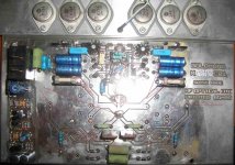
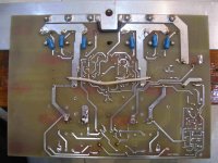
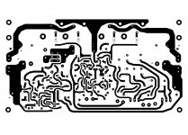
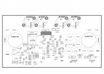
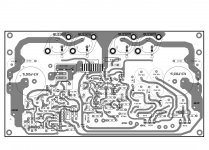
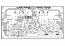
Thank you nikosokey, these attached files are what I've got.
I would like to know if these are good and if they reflect the last changes.
Maybe these last changes are just about part numbers but I am in doubt because I've seen a different board with component silkscreen, etc.
http://www.diyaudio.com/forums/solid-state/174468-very-best-amplifier-i-have-ever-heard-104.html #1034
The power supply has different voltages, and the protection circuit is shown in a separate, hand draft schematic.
If the board is good, I will follow the steps about changes made, and if not please tell me if I can still get a pair of new upgraded PCB's.
Thank you.
Attachments
-
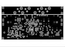
 Mimesis 3 Layout 55.JPG452.2 KB · Views: 325
 -
 Mimesis 3 Layout 44.JPG465.8 KB · Views: 306
 -
 Mimesis 3 Layout 33.JPG644.3 KB · Views: 316
 -
 Mimesis 3 Layout 22.JPG644.3 KB · Views: 347
 -
 Mimesis 3 Layout 11.JPG586.2 KB · Views: 339
 -
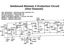
 Goldmund Mimesis 3 Final Protection Circuit Schematic 2.jpg164.8 KB · Views: 284
 -
 Goldmund Mimesis 3 Final Protection Circuit Schematic 1.jpg262 KB · Views: 813
 -
 Goldmund Mimesis 3 Final Power Supply Schematic.jpg327.9 KB · Views: 898
 -
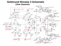 Goldmund Mimesis 3 Final Schematic.JPG500.2 KB · Views: 954
Member
Joined 2009
Paid Member
Whatever you do, don't assume a simple relay will protect your speakers. There's much written about that around here. At the very lease, use a relay that switches the speaker from the amp output to ground - so you need at least a SPDT relay contact. Search for Rod Elliot's stuff on this topic on his website - note the comments on using a simple diode to protect from the relay motor back e.m.f. slowing down it's response and how he addressed that. A solid state relay (DIY versions on this forum) may be a better choice.
Thank you Bigun, but as you can see, I am in the process of detecting if the boards I have are good and if they need upgrades. So far I didn´t get an answer. The relay issue could be next, but first things first.
I have read many good articles from Rod Elliot from his website in the last years.
Thank you again.
I have read many good articles from Rod Elliot from his website in the last years.
Thank you again.
Golmund clone
Welcome to "Goldmund clone club". I understand why you might feel a bit insecure and perhaps confused by the many posts and opinions on this construction in a very long thread. It may seem hard to get a good overview. Some were very critical, yes, I would argue excessively negative. Much also came to be about one person (thread starter), which you suggest yourself. There are some members here on DIYaudio having well-built copies of this clone, and thus to a certain extent, has made the biggest skeptics to shame.
You have a PCB, and you have, from what I understand, most components. I have no doubt that Nagys print is completely o.k. (a quick glance shows that it is quite close to Alex's ). Some changes, however, I would suggest:
1. Replace T 11/12 with BSS 71/74 and make sure that they get cooling.
2. T7, T8, T9 and T10 gets hot too. You can replace MPSA42/92 with
MJE340/350 and mount cooling on these. You will find some suggestions on
such a solution in the thread.
3. Nikosokeys recommendations to separate ground plane should certainly
be considered. Although I have chosen a different solution by allowing
VAS and predrivers to have their own power.
4. For power supply:: Follow Nagy's suggestion, you are going to build a
Goldmund 3 and notb a Golmund 9!!!
Dot hesitate, go ahead. Good luck.
Eivind Stillingen
Thank you Liliya for your kind and precise reply.
I feel that many of the participants maybe a little tired about this project, so I can understand that they may also be a little reluctant to keep on giving information and support , specially for "late newcomers" as me. Special thanks for the received replies then.
In the other hand - and with all my respect for everybody here - (including those who argued and showed negative positions) I trusted the initiative from the first moment and tried to contribute with good vibes. I am sorry that my own activities forced me to be absent at the moment of assembly and testing, having tho keep almost 99.9% of the parts in a box.
As I said before, I will not issue any kind of "political" opinion about NagysAudio because I really feel that he acted on a "bonafide" basis and when I had private contact with him buying the boards, he behaved as a gentleman with me, despite that I could be critical about some aspects of the schematics presentation. It seems to me that the outstanding level of this forum and of its members has no relation with some conflicts I read of along the posts of the thread, some passages are (to my surprise) very discouraging and sad, everytime I think that this place should be a space for the best human knowledge sharing and contributing, an opportunity to relax and enjoy what we all love (electronics + best audio), and for me particularly, one of the best places to hear people like you, and learn from every thought and advice.
Perhaps this could be a good opportunity at this point to resume these apparently confusing inconsistencies.
Some of my doubts at this point are the following, regarding all the contributions and research done:
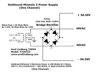
1. the power supply voltages in my original schematic is +/- 56.5 V and don't know if this is finally OK or requires changes.
2. the power transformer for one single channel should be Avel Lindberg 330 VA model # Y236753 (or equivalent rating) for 200 W output power over 3 Ohms load.
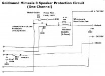
3. regarding the protection circuit (please see the hand made draft original files uploaded by me recently) I have no annotation for the parts, so I can't tell if the thread is referring to issues with components included in this particular section of the amplifier. I guess if this section works fine and if some changes apply here. A final neat schematic would be very much appreciated if exists. If somebody has a real up to date final schematic including the protection circuit, please let me know where to find it.
4. the moulded 22 turns output coil indicates winding over a .22 Ohm 3W wirewound resistor. I have read that 22 Ohms could be better to avoid the resistor to short the coil inductance.
5. my version of the amplifier complete schematic does not include the alteration needed for the insertion of the protection circuit that apparently my version of the PCB includes and works fine (?)
6. there is an offset adjust through R8 220 Ohms trimpot, but I heard in your post about the convenience of adding a quiescent current adjustment trimpot that I don't know if applies to my circuit version.
7. my schematic indicates (and I have purchased effectively from Newark) BUZ900 / BUZ905 MOSFET's. Some members talked about the absence of source equalizing resistors, so the matching of the MOSFET's becomes mandatory. Being myself in Argentina, I can't buy 100 MOSFET's to get 4 matched units. How can I match these MOSFET's ?
8. about "Nikosokeys recommendations to separate ground plane" I don't know if I have the skills to make these many cuts that are not very clear to me watching the pictures. Should this point justifies to buy the bigpanda boards ?
9. are these bigpanda boards available ? do they reflect the many changes ? Am I in time to change PCB's before making all this surgery on my version of PCB's ? I have the original Panasonic relay.
10. which is the difference between Goldmund 3 and Goldmund 9 ? bigpanda's boards are 6 output devices, is this a Goldmund 9 ?
These are the main doubts I have about the project, and specially I couldn't find many opinions about the finished results except for yours. As I said, this could be an opportunity to write a resume about the changes done to the original schematic and PCB's
Could you help me write it so other members in my situation can also build and enjoy this amplifier ?
Thank you very much for your and other members appreciated efforts.
I feel that many of the participants maybe a little tired about this project, so I can understand that they may also be a little reluctant to keep on giving information and support , specially for "late newcomers" as me. Special thanks for the received replies then.
In the other hand - and with all my respect for everybody here - (including those who argued and showed negative positions) I trusted the initiative from the first moment and tried to contribute with good vibes. I am sorry that my own activities forced me to be absent at the moment of assembly and testing, having tho keep almost 99.9% of the parts in a box.
As I said before, I will not issue any kind of "political" opinion about NagysAudio because I really feel that he acted on a "bonafide" basis and when I had private contact with him buying the boards, he behaved as a gentleman with me, despite that I could be critical about some aspects of the schematics presentation. It seems to me that the outstanding level of this forum and of its members has no relation with some conflicts I read of along the posts of the thread, some passages are (to my surprise) very discouraging and sad, everytime I think that this place should be a space for the best human knowledge sharing and contributing, an opportunity to relax and enjoy what we all love (electronics + best audio), and for me particularly, one of the best places to hear people like you, and learn from every thought and advice.
Perhaps this could be a good opportunity at this point to resume these apparently confusing inconsistencies.
Some of my doubts at this point are the following, regarding all the contributions and research done:
1. the power supply voltages in my original schematic is +/- 56.5 V and don't know if this is finally OK or requires changes.
2. the power transformer for one single channel should be Avel Lindberg 330 VA model # Y236753 (or equivalent rating) for 200 W output power over 3 Ohms load.
3. regarding the protection circuit (please see the hand made draft original files uploaded by me recently) I have no annotation for the parts, so I can't tell if the thread is referring to issues with components included in this particular section of the amplifier. I guess if this section works fine and if some changes apply here. A final neat schematic would be very much appreciated if exists. If somebody has a real up to date final schematic including the protection circuit, please let me know where to find it.
4. the moulded 22 turns output coil indicates winding over a .22 Ohm 3W wirewound resistor. I have read that 22 Ohms could be better to avoid the resistor to short the coil inductance.
5. my version of the amplifier complete schematic does not include the alteration needed for the insertion of the protection circuit that apparently my version of the PCB includes and works fine (?)
6. there is an offset adjust through R8 220 Ohms trimpot, but I heard in your post about the convenience of adding a quiescent current adjustment trimpot that I don't know if applies to my circuit version.
7. my schematic indicates (and I have purchased effectively from Newark) BUZ900 / BUZ905 MOSFET's. Some members talked about the absence of source equalizing resistors, so the matching of the MOSFET's becomes mandatory. Being myself in Argentina, I can't buy 100 MOSFET's to get 4 matched units. How can I match these MOSFET's ?
8. about "Nikosokeys recommendations to separate ground plane" I don't know if I have the skills to make these many cuts that are not very clear to me watching the pictures. Should this point justifies to buy the bigpanda boards ?
9. are these bigpanda boards available ? do they reflect the many changes ? Am I in time to change PCB's before making all this surgery on my version of PCB's ? I have the original Panasonic relay.
10. which is the difference between Goldmund 3 and Goldmund 9 ? bigpanda's boards are 6 output devices, is this a Goldmund 9 ?
These are the main doubts I have about the project, and specially I couldn't find many opinions about the finished results except for yours. As I said, this could be an opportunity to write a resume about the changes done to the original schematic and PCB's
Could you help me write it so other members in my situation can also build and enjoy this amplifier ?
Thank you very much for your and other members appreciated efforts.
Liliya BTW . . . I forgot something:
In my set of original schematics I think that your component annotation does not apply. This is the main reason why I am kindly asking for an updated copy of the schematics.
1. Replace T 11/12 with BSS 71/74 and make sure that they get cooling.
2. T7, T8, T9 and T10 gets hot too. You can replace MPSA42/92 with
MJE340/350 and mount cooling on these. You will find some suggestions on
such a solution in the thread.
In my set of original schematics I think that your component annotation does not apply. This is the main reason why I am kindly asking for an updated copy of the schematics.
Attachments


- Home
- Amplifiers
- Solid State
- The Very Best Amplifier I Have Ever Heard!!!!