Sir TRMS DMM is to expensive for me .I have only dmm .I know that I need but can't adorable for me . Because I am not belong rich family.is that any way to solve this 😢😢😢
hi there sir Sunny22g
i had taken a look at your work seems ok, do not worry about the DMM i made my first B500 and AX14 with analog multimetre only.
bear in mind these module has been made by DIYers and most of them satisfied with the result, so might be the factors will be from us to wit
a. quality of materials though they are not genuine atleast measure it one by one before soldering it, i had been a victim of some counterfeit before but still it work just a little low on efficiency. (now i buy parts from authorized dealers only)
b. did you place some lamp on the other side of the board after soldering to check if some tracks were not shorted? i do that all the time.
c. in cases of doing all means but still does not work you CAN solder all tracks sometimes it can have gaps due to overly soak to etching compound.
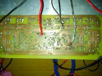
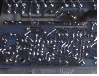
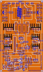
i am uploading back your picture and my sample of soldering all tracks
Attachments
hi there sir Sunny22g
i had taken a look at your work seems ok, do not worry about the DMM i made my first B500 and AX14 with analog multimetre only.
bear in mind these module has been made by DIYers and most of them satisfied with the result, so might be the factors will be from us to wit
a. quality of materials though they are not genuine atleast measure it one by one before soldering it, i had been a victim of some counterfeit before but still it work just a little low on efficiency. (now i buy parts from authorized dealers only)
b. did you place some lamp on the other side of the board after soldering to check if some tracks were not shorted? i do that all the time.
c. in cases of doing all means but still does not work you CAN solder all tracks sometimes it can have gaps due to overly soak to etching compound.
i am uploading back your picture and my sample of soldering all tracks
Greetings Sir Sam I am fully satisfied with u .Sir. Tell me if PCB components are touched with other then it's mean some thing Short .And series bulb brighter.but bulb is no brighter.and if short with in 1 min components are burn.but they are not burn
I don't think it means you will have a short, it could be that you are turning on or off the wrong transistor, or pushing current through a cap (that can take it) but shouldn't see that signal.
Just because you have incorrect soldering, does not always mean a short is the result.
Use your DMM to check for continuity in those areas, if so, then correct the soldering and check again. Always start with the easiest things and then move to actually removing parts and testing out of circuit.
Just because you have incorrect soldering, does not always mean a short is the result.
Use your DMM to check for continuity in those areas, if so, then correct the soldering and check again. Always start with the easiest things and then move to actually removing parts and testing out of circuit.
Greetings Sir Sam I am fully satisfied with u .Sir. Tell me if PCB components are touched with other then it's mean some thing Short .And series bulb brighter.but bulb is no brighter.and if short with in 1 min components are burn.but they are not burn
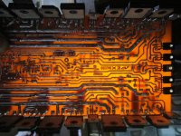
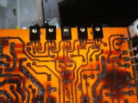
hi sir, when i told you to use lamp i do NOT mean the series bulb tester but it should be used to look for short/broken tracks like this process see attached picture coz that is the way i checked the tracks aside from continuity tests.
do not expect us to be able to diagnose if the tracks are shorted to each other. WE only suggest to check those points, but it is you who can assess the precision. Now it seemed that you do not measure voltages of your amp that is why nobody can give advice. people here needs data if you do not give their request then do not expect for answers.
if you start all over again that is ok but it will not teach you troubleshooting problems. you cannot solve problems by avoiding but by facing it.
Attachments
yes it is.
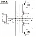
First I want to thank Apex for the development of the amplifier and you for the layout of the PCB. I'm using your PCB, but I did not quite understand how to do ac ac connection. What is the voltage to be connected to AC AC (protection)? If I have difficulty, can I use another protection like the NE555?
Sorry, writing too fast ended up deleting some words. First of all I would like to thank Apex for the development of the amplifier and the 44250 for the layout of the PCB sr150. I'm using your PCB, but I did not quite understand how to make a ac ac connection. What is the voltage to be connected to AC AC (protection)? If I have difficulty, can I use another protection like the NE555?
ac ac goes to ac-ac secondary of psu transformer. if one secondary part of transformer for any reasnon looses voltage,that will result in voltage drop wich supplies relay and it will open it's contacts. you can use any protection you wish,just don't put parts of protection on SR150 board,and use external as usually.
.
resistance in series with relay could be a bit pain to adjust right,you should use 24V relay and than adjust that resistor in series with such value to achieve 24V at relay coil.
.
resistance in series with relay could be a bit pain to adjust right,you should use 24V relay and than adjust that resistor in series with such value to achieve 24V at relay coil.
ac ac goes to ac-ac secondary of psu transformer. if one secondary part of transformer for any reasnon looses voltage,that will result in voltage drop wich supplies relay and it will open it's contacts. you can use any protection you wish,just don't put parts of protection on SR150 board,and use external as usually.
.
resistance in series with relay could be a bit pain to adjust right,you should use 24V relay and than adjust that resistor in series with such value to achieve 24V at relay coil.
Thanks for the directions, your help was very helpful. I had to stop the project momentarily, but soon I want to return and assemble it, I'm sure the sound is very good, after all the Apex amplifiers are the most assembled in the DIY world and this is no accident. Thanks apex for the project and 44250 and others who develop the PCBs.
Is it possible to feed two sr150, with this PSU, with 2 pairs?
Hello, do I need to make any modifications to PSU 05 if 25 VAC or 35 VAC is used?
Grateful

Hello, do I need to make any modifications to PSU 05 if 25 VAC or 35 VAC is used?
Grateful
Use 6V2 instead 12V zeners.
- Home
- Amplifiers
- Solid State
- Studio Reference Amplifier