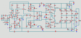
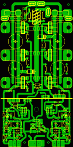
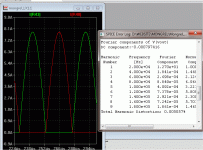
I'll just point out that by pre-filtering using an active Twin-T notch filter to drop the level of the fundamental down 60dB, so that the residual distortion of the sound card will be below the noise, using even ordinary sound cards with spectrum analyzer software like ARTA can let you see the products of mid-band frequencies at levels below 10ppm.
For signals over 10kHz, you need 192kHz sampling. At 20kHz, however, even a sound card with 192kHz sampling will not let you see the 5th harmonic. 18kHz is a nice substitute frequency in this case. I generally like to see up to the 9th H. if possible.
My PC's 24-bit/96kHz sound system lets me easily see products in the 1ppm area and well below.
Hi Bob,
Thanks for this extended explanation.
The principle look valid , although as you pointed it, preventing
magnetic fields from radiating on sensitive parts of the design
is surely the most efficient solution..
As an eventual solution, putting big caps near the OS with a low R
resistor in serial with the supply rail..
This will not prevent magnetic fields but the wire path current
waveform will be better integrated (mathematically speaking)
and thus, the AC current variation due to signal currents will
be of lower amplitude and longer period through the said wire,
allowing to be closest to a statical magnetic field caracteristics..
Hi wahab,
Yes, placing caps right at the output stage to integrate the currents right there is also something that I advocate. Although I've never done it, I have actually wondered if maybe the rail wires leading from the power supply (twisted, of course) should actually be small to create some very small amount of resistance
Cheers,
Bob
Hi wahab,
Yes, placing caps right at the output stage to integrate the currents right there is also something that I advocate. Although I've never done it, I have actually wondered if maybe the rail wires leading from the power supply (twisted, of course) should actually be small to create some very small amount of resistance.
Cheers,
Bob
The OEM's do it.
 Acts as a current limit and a "poor man's" CRC. Just a observation , .... but they seem to "tune" the values of the local PCB decoupling caps to the cabling. In my search for the truth , more "mysteries" -
mystery about inductance of lead wire
came up
the graphs have confused me.
I can't find R26 (pre-driver current varying from 27.2uA to 28.6uA i.e. +-0.7uA)
R35 does not measure Driver current. Ir35 shows up the variation in the bias voltage as the feedback tries to correct for the different drive requirements of the ClassAB output stage to maintain low distortion during the crossover.
You need to add in a dummy resistor on the Emitters of the drivers to read Driver current.
Why are the peak R35 currents varying alternately when the output is changing from +ve flow to -ve flow cf. from -ve flow to +ve flow?
I built it ! Bob's "tip" about using low Vce/high beta devices led me to the sb1151/sd1691 pair (to-126).On my LT plots , R26 was just a arbitrary value (a "dummy Resistor") to plot the uA's. Using higher gain pre-drivers , this is most likely far lower.
. you are correct , R35 is just the steady bias of the drivers at rest (or at minimal load).Loaded with 1-2R , the actual driver current is in the 100's of mA. As far as driver "dummy resistors" , LT lets you probe the collectors directly to measure current. "Dummies" are only useful to plot total stage current or to add "errata" to a circuit , approximating real world performance.
Simulation is just a step in the process to "make it so" (capt. picard ).
On the real thing , the 1151/1691 pair gave me awesome beta ! With the worse case OP beta (21193/4's) and a near short as a load , expect over one million current gain and the VAS load at under .1ma. The CCS's do most of the work leaving the pre-drivers to soar. Only 2.1V C-E !! Some will fuss about adding 6 more devices to the circuit , but I see it as a well spent $1.80. Awesome addition to any worthy voltage stage ... thanks, Bob.
PS , EF2's are so "yesterday" now.
OS
Well that is certainly an interesting topology, lots of transistors and boosted front end supply rails all adding to cost and complexity. This is probably a good time to ask the question, Bob, do you really think you (or some of the best trained listeners) could pick out one of these advanced topologies as compared to some of the better but much simpler ones in a blind A/B test?
As I've mentioned before, my brother and I were both highly interested in amplifier design decades ago and this is where we ended up. Sure it is challenging to design out as many non-linearities as possible but there are only so many hours in the day and one should ask is this the best use for our time - might our time be better spent designing better loudspeakers for example. It should reach a point where the question arises - where is the threshold of audibility?
If this is a relaxing passtime for some then sure go ahead and spend as much time as you like - but the question is certainly valid.
I am aware of Geddes' work on the audibilty of distortion - yes I know it is complex.
Last edited:
Just thought I'd mention Bob that I used your device models in a simulation of the old Universal Tiger amplifier and found some rather odd behavior. I expected to see cross conduction, but most likely less with the faster NJL outputs as compared to the MJL outputs. Instead the NJLs showed cross conduction whereas the MJLs did not. Also, the PNP MJL had a rather high saturation voltage of about 4.5 Volts at 10A peak, I expected to see closer to 2 Volts. Just looked up the spec and it is 1.4 V Vce Sat at 8A. The PNP part does have more beta droop but it seems to be more than it should be.
I do appreciate all the work that you did and that you made these available but I was wondering if you noticed this issue.
Here's a link to the simulation files in case you are interested:
http://www.diyaudio.com/forums/soli...-tiger-improved-simulation-2.html#post2583843
I dug into it a bit more and it might be caused by the higher beta droop of the PNP device, I was using a 4 ohm load and it does better into 8 ohms.
I don't usually see this in real life, and one reason might be that the worst case beta of 25 at 8A is at TJ of 25 deg C, the outputs get hot when driven hard like this and beta goes up with temp so typically this amp would go within about 2 volts of the rail even with a 4 ohm load.
Last edited:
Well that is certainly an interesting topology, lots of transistors and boosted front end supply rails all adding to cost and complexity. This is probably a good time to ask the question, Bob, do you really think you (or some of the best trained listeners) could pick out one of these advanced topologies as compared to some of the better but much simpler ones in a blind A/B test?
As I've mentioned before, my brother and I were both highly interested in amplifier design decades ago and this is where we ended up. Sure it is challenging to design out as many non-linearities as possible but there are only so many hours in the day and one should ask is this the best use for our time - might our time be better spent designing better loudspeakers for example. It should reach a point where the question arises - where is the threshold of audibility?
If this is a relaxing passtime for some then sure go ahead and spend as much time as you like - but the question is certainly valid.
I am aware of Geddes' work on the audibilty of distortion - yes I know it is complex.
Hello Pete
What is your benchmark for a good sounding power amp.
Regards
Arthur
Hello Pete
What is your benchmark for a good sounding power amp.
Regards
Arthur
I don't follow the question, do you mean make and model?
How about giving your example if this is what you intended.
By PB2 -Well that is certainly an interesting topology, lots of transistors and boosted front end supply rails all adding to cost and complexity. This is probably a good time to ask the question, Bob, do you really think you (or some of the best trained listeners) could pick out one of these advanced topologies as compared to some of the better but much simpler ones in a blind A/B test?
Being dirt poor , I also must weigh out the cost/complexity to final sound equation (very carefully). For the OP , the BJT "DBT" with 15 devices = a 8 device lateral setup. The DBT costs $20 for the silicon , 6 renesas laterals cost $24-30. Once the PCB is done, it might take another $1.80 and a few more minutes to stuff the board. At a larger scale (5-6 pair of outputs) the BJT's rule.
A 350W/ 6 pair BJT triple output stage can be made for under $40.
I have 2 pair of the original hitachi to-3 laterals to compare to. Very easy to do , 1 trimmer , 4 stoppers ... listen.
"Boosted front end" supplies will give the amp a noticable dual mono effect with a standard single OPS supply. (yes , you can hear this).
OS
"Boosted front end" supplies will give the amp a noticable dual mono effect with a standard single OPS supply. (yes , you can hear this).
OS
I have seen your posts where you make claims of hearing all sorts of things. I seriously doulbt that you can hear a boosted front end supply as long as you keep both amps out of clipping. There is little point in continuing since unless we do the experiment there is no way of proving the outcome, but I am interested in hearing Bob's opinion.
I don't follow the question, do you mean make and model?
How about giving your example if this is what you intended.
Hello Pete
I mean at home when you listen to your hifi what amp do you use in your system. I am assuming you like the sound of it.
Regards
Arthur
HI
Sorry to ask, but what is a "DBT" ?
Double Blind Test of course!
Just to confuse people , I suppose I will do DBT on a DBT. Too many acronyms .... too lazy to write the wordz. 
I also agree to disagree ... If you have to do a (D)ouble (B)lind (T)est , the change or improvement to your circuit is not worthy.
On to loudspeakers , both my pairs have dayton softdome tweeters with 1st order 250v poly Xover caps. 125mm Dayton midranges w/20oz magnets on the big speakers and OEM paper cone woofers on both (need better ones). I can hear very fine details. OEM tweeter/ mids - no way to decern subtle changes in topology or separation.
OS
I also agree to disagree ... If you have to do a (D)ouble (B)lind (T)est , the change or improvement to your circuit is not worthy.
On to loudspeakers , both my pairs have dayton softdome tweeters with 1st order 250v poly Xover caps. 125mm Dayton midranges w/20oz magnets on the big speakers and OEM paper cone woofers on both (need better ones). I can hear very fine details. OEM tweeter/ mids
OS
Last edited:
I have seen your posts where you make claims of hearing all sorts of things. I seriously doulbt that you can hear a boosted front end supply as long as you keep both amps out of clipping. There is little point in continuing since unless we do the experiment there is no way of proving the outcome, but I am interested in hearing Bob's opinion.
Hi Pete,
I usually like to use boosted rails for the IPS-VAS in my amplifiers that strive for highest performance. There are a couple of reasons for this, but simply using boosted supplies will not automatically result in better sound. Its what they let you do to improve the circuits.
For me, the key is that the boosted supplies provide more headroom for the whole input section so that there are more design choices and fewer constraints in making a high-performance IPS-VAS. I first used boosted rails in my MOSFET power amplifier with EC because I was using a VAS with cascodes, etc. I never wanted the VAS to come even close to a region of voltage headroom discomfort. In that amplifier, the boosted rails also helped with the fact that the MOSFETs needed more turn-on voltage than BJTs.
If you don't use boosted rails, you may waste precious headroom in the main high-current power supply. In the overall scheme of things, those extra volts from a low-current boosting supply are quite inexpensive.
The use of boosted rails also give you the opportunity to really do a good job filtering the supplies to the IPS-VAS, more effectively keeping power supply noise, ripple, etc away from those more sensitive parts of the amplifier.
It is undoubtedly true that the addition of boosted rails will add to the cost of the amplifier, but if we are talking about really high performance amplifiers it is but one of many more higher costs.
Cheers,
Bob
I was certainly aware of all that Bob, and that MOSFET output amps need more drive to reach the rails.
I'm more interested in your response to my posts #1806 and #1807.
Especially with regard to the threshold of audibility.
I do understand that for example a company might hire you to design an ultimate amp and then one might choose to add components in order to have the best specs for whatever reason. But generally we do not design in a cost is no object mindset so it would seem that my question still applies.
- Home
- Amplifiers
- Solid State
- Bob Cordell's Power amplifier book


