Yes, there is. Nodes either side of R1 are labelled "r" and "b" respectively. These nodes are then connected to C1 and C3 respectively.
Ahh - missed that, sorry.
Jan
It is even more better to use this transistor in a cascode configuration. Then it not only "neutralizes" the Miller capacitance, but also greatly reduces the Early effect.take diff ips (bjt) ---- connect a value of c to collector of one and to base of other. do it that way to both bjt.
Roughly, if the C are same as ips c's, they cancel.
You can use a backwards diode or better, another transistor as diode of same type as ips diff. and get better dynamic cancellation using diode C.
[...]
Cheers, E.
Yes, I like to do that, it keeps the drawing clear and clean (but than... adds it's own mechanism of confusion).
What can help here is to use node symbols rather than just letters - makes it more obvious that something’s connected.
It also fixes it by doing the tail current source as an independent feedback current source, which is the way it should have been done in the first place.
Indeed, and as pointed out in all the APAD books since the first edition.
See the slew-rate chapter.
By obtaining the bias for the tail current source transistor from the VAS feedback current source, you lost all of the Early effect immunity that would have been achieved simply by using a separate feedback current source for the LTP.
Not sure I follow you there. How does that work?
It is even more better to use this transistor in a cascode configuration. Then it not only "neutralizes" the Miller capacitance, but also greatly reduces the Early effect.
Cheers, E.
true or do both. Just another way .. cheap simple way. However, if you use other topologies, you can do cancelling of C inherently and have very low distortion also. Kinda like distortion cancellation vs reduction.
THx-RNMarsh
Last edited:
On CMOS ICs like the figure in post #8510, cascodes are not preferred because they eat up sizeable fractions of the available supply voltage. Positive feedback neutralization does not.
However in discrete circuit design where a low supply voltage is not dictated by the marketing department, cascodes are less problematic.
However in discrete circuit design where a low supply voltage is not dictated by the marketing department, cascodes are less problematic.
On CMOS ICs like the figure in post #8510, cascodes are not preferred because they eat up sizeable fractions of the available supply voltage. Positive feedback neutralization does not.
However in discrete circuit design where a low supply voltage is not dictated by the marketing department, cascodes are less problematic.
yes, that is very much a factor.... I might add more detail to it.. additional cascode transistors and their biasing etc and real-estate on die is greatly increased.... increasing costs. However, 'problematic' is probably not an issue... at least I never found it to be for audio/LF.... experimentally. Any method which has the potential to increase stage BW, increases the potential for HF osc. For purely CAD guys more accurate knowledge of device characteristic/modeling is perhaps needed. Including pcb layout and grounding. In this case, increased BW is a by-product of attempting to reduce distortion caused by the non-linear device C's.
THx-RNMarsh
Last edited:
Regarding input current distortion, I remember years ago when andy_c was trying to get the
diff pair input stage distortion as close to zero as possible in simulation. IIRC he was surprised
by the level of complexity that was required, mirror the mirror, cascode the current
sources, etc.
He posted a simulation here where his schematic can be seen, not sure if this will shed any
light on the input current distortion question and I'm too lazy to dig into it again but thought it
might be of interest to others - nice work as usual andy_c:
http://www.diyaudio.com/forums/soli...nterview-negative-feedback-4.html#post1112619
Andy on the unrelated topic of PIM:
Extension of Gilbert
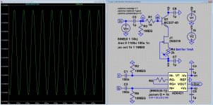
And here my results, actually my non-results, if there is anyone out there who can measure the distortion in a 10mVAC signal (my QA400 is not made for that) and want to give it a try, send me your address and I will send you the experiment.
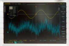
The only thing that I can confirm from my measurements, the reality matches the simulations, and the AC base current is about 1uA (10mV out divided by 1000 is 10uV in measured over 10 Ohm equals 1uA AC or there about).
It also seems that my lab is way to noisy
The only thing that I can confirm from my measurements, the reality matches the simulations, and the AC base current is about 1uA (10mV out divided by 1000 is 10uV in measured over 10 Ohm equals 1uA AC or there about).
It also seems that my lab is way to noisy
Attachments
It is really unfortunate that andy_c, GK, mikeks, Ovidiu (forget his forum name) and
several others have left this forum.
Ovidiu's page: PGP
GK's page: Glen's Stuff his audio stuff is either gone or on another page
Glenn did an update of Bob's SV oscillator
years ago: SV Oscillator PCB group buy
several others have left this forum.
Ovidiu's page: PGP
GK's page: Glen's Stuff his audio stuff is either gone or on another page
Glenn did an update of Bob's SV oscillator
years ago: SV Oscillator PCB group buy
Last edited:
Regarding input current distortion, I remember years ago when andy_c was trying to get the
diff pair input stage distortion as close to zero as possible in simulation. IIRC he was surprised
by the level of complexity that was required, mirror the mirror, cascode the current
sources, etc.
He posted a simulation here where his schematic can be seen, not sure if this will shed any
light on the input current distortion question and I'm too lazy to dig into it again but thought it
might be of interest to others - nice work as usual andy_c:
http://www.diyaudio.com/forums/soli...nterview-negative-feedback-4.html#post1112619
Thanks for this.
Inverting mode eliminates most of the common mode input voltage and so eliminates the need for a tracking cascode on the LTP. But in that case you have to choose between high noise, high source load, or an input buffer.
Inverting mode doesn't put the input stage in the feedback loop however. I'm not sure it's even possible to put the input stage inside the feedback loop.
After a certain point, a tracking cascode on the LTP is the only way to reduce distortion on a non-inverting amp. Only after adding that feature is it useful to look for other distortion mechanisms. Usually this is well below 0.002%THD in simulation in my experience.
Last edited:
Inverting mode doesn't put the input stage in the feedback loop however. I'm not sure it's even possible to put the input stage inside the feedback loop.
Hello Keantoken,
Are you sure that the input stage in not in the feedback loop when its configured in inverting mode. I dont see it like that, I think its in the feedback.
Hello Keantoken,
Are you sure that the input stage in not in the feedback loop when its configured in inverting mode. I dont see it like that, I think its in the feedback.
A feedback loop compares the input and output of a system and subtracts the error from the input. There is no mechanism (unless explicitly intended) which subtracts the common mode error of the LTP from the amp's input whether in inverting or non-inverting mode. Inverting mode simply has the advantage that it doesn't generate common mode distortion in the LTP.
The error voltage that occurs between positive and negative inputs is not divided by open loop gain, it simply adds to the output while being multiplied by CLG.
Fortunately, the distortion of an LTP used this way is astoundingly low even without tracking cascodes. In an ironic twist this ceases to amaze anyone, although we eagerly bicker back and forth about whether the figures in simulations can be achieved in real life.
Strange rhetoric.There is no mechanism (unless explicitly intended) which subtracts the common mode error of the LTP .
Inverting mode simply has the advantage that it doesn't generate common mode distortion in the LTP.
Inverting mode eliminates most of the common mode input voltage and so eliminates the need for a tracking cascode on the LTP. But in that case you have to choose between high noise, high source load, or an input buffer.
Inverting mode doesn't put the input stage in the feedback loop however. I'm not sure it's even possible to put the input stage inside the feedback loop.
After a certain point, a tracking cascode on the LTP is the only way to reduce distortion on a non-inverting amp. Only after adding that feature is it useful to look for other distortion mechanisms. Usually this is well below 0.002%THD in simulation in my experience.
You are right. Years after I published my MOSFET Power Amplifier with Error Correction, I modified it to include tracking in the cascode it already had, and that modification further reduced distortion. I referred to that arrangement as a "driven cascode" because the signal voltage applied to the cascoded bases was derived from a replica feedback network from the amplifier output. I did it this way because I did not want to add complexity to the existing IPS and possibly compromise its performance by hanging anything off of the tail. The driven cascode requires only passive components to implement - namely the replica feedback network. In this arrangement, the shunt arm of the replica feedback network is just connected to the +15V supply that would otherwise have been biasing the cascode bases.
Cheers,
Bob
Strange rhetoric.
I never went to school for rhetoric, so feel free to make corrections.
You are right. Years after I published my MOSFET Power Amplifier with Error Correction, I modified it to include tracking in the cascode it already had, and that modification further reduced distortion. I referred to that arrangement as a "driven cascode" because the signal voltage applied to the cascoded bases was derived from a replica feedback network from the amplifier output. I did it this way because I did not want to add complexity to the existing IPS and possibly compromise its performance by hanging anything off of the tail. The driven cascode requires only passive components to implement - namely the replica feedback network. In this arrangement, the shunt arm of the replica feedback network is just connected to the +15V supply that would otherwise have been biasing the cascode bases.
Cheers,
Bob
Clever Bob! Do you think a bootstrap C from the original fb network might also work?
Jan
Clever Bob! Do you think a bootstrap C from the original fb network might also work?
Jan
It might, but my preference is to avoid anything that could compromise the critical feedback node in any way.
Cheers,
Bob
- Home
- Amplifiers
- Solid State
- Bob Cordell's Power amplifier book