what that did was increase the distortion to .01%
This should not happen unless the amp has been crippled somehow. Did you follow the rest of the directions from post 606?
http://www.diyaudio.com/forums/solid-state/169590-mongrel-supersym-ii-13.html#post2314453
I usually get 3-22nF for the capacitor.
- keantoken
I could just remove it ?? It is just CCS related. dang , it works good .. I just simulated the biggest transient my PB250 can output (130v p/p) still .0001% at 1Khz ... direct newton, no tseeds , operating point recalculations or any other glitches. LT is very verbose in it's "complaints". The only other amp that will sim this flawlessly with no "complaints" is the BX/DX (simple bootstrap amp).
OS
OS
This should not happen unless the amp has been crippled somehow. Did you follow the rest of the directions from post 606?
http://www.diyaudio.com/forums/solid-state/169590-mongrel-supersym-ii-13.html#post2314453
I usually get 3-22nF for the capacitor.
- keantoken
I did ,went up to 100R with the resistor and the distortion went down to .0008% but not to the psycho levels with 5600p/68-150R as the R/C. My 5pF direct from the KSA1381 collector to the first differential is almost the same as "piggybacking" it on the main GNFB... both are lead comp ?? are they not ??
OS
I just reproduced your results on distortion, looks like I was wrong this time.
You are right, both are lead comp. What OPS are you using? I can't get my simulation stable.
- keantoken
I'm using my only "test jig" , the PB250 (4 pair OPS). I can't understand why you can not get it stable... IT IS!!
below is the most current , even set at 130V p/p 1k ..
")
OS
Attachments
OS, extend your .AC simulation to 100MHz, I suspect you will see something disturbing.
EDIT: nevermind, base stoppers on the outputs... yeah...
- keantoken
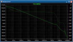
you mean the double hump ?? I usually just go out to 10e6 , at 10e7 I see. Is this even valid ??, the NJW OP's don't even have an Ft of 40 mhz. I might be worried if I was using IRF MOSFETS. As B. Cordell explained, they can oscillate above the freq. our cheap 20mhz scopes can even show.
BTW, the 40mhz "bump" is at -50DB AFTER the UG point. The 180 degree danger zone (oscillation) would not occur till 4mhz/180 degrees which is at
-10DB.
plot 1 is the PX.. plot 2 is the GX (it does not have this "artifact"). Maybe I should compensate globally (the 5pF) or even reduce the gain a tad (degenerate LTP2).
OS
Attachments
Last edited:
Anyways, without base stoppers there is a resonance spike above 0db on the OLG plot, and thus oscillation. This is why I go to at least several hundred MHz by default. Perhaps not guaranteed in the "real world", but it still matters... Even if in real life it's not the same, at least you will know what to do if you run into problems, after correcting them in the simulator.
I've got sims of both compensation schemes working now, but your version has a prominent 5th harmonic. Output stage bias setting affects these harmonics largely. Can I see a plot of d(V(Vout,VcQ8)? This will highlight what I'm looking for to get similar results when adjusting the bias network.
- keantoken
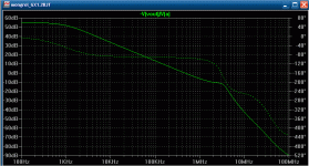
you mean the double hump ?? I usually just go out to 10e6 , at 10e7 I see. Is this even valid ??, the NJW OP's don't even have an Ft of 40 mhz. I might be worried if I was using IRF MOSFETS. As B. Cordell explained, they can oscillate above the freq. our cheap 20mhz scopes can even show.
BTW, the 40mhz "bump" is at -50DB AFTER the UG point. The 180 degree danger zone (oscillation) would not occur till 4mhz/180 degrees which is at
-10DB.
plot 1 is the PX.. plot 2 is the GX (it does not have this "artifact"). Maybe I should compensate globally (the 5pF) or even reduce the gain a tad (degenerate LTP2).
OS
Okay, let me slobber over this bone for a bit...
The "bump" is caused by the Cob of the outputs (doesn't matter how fast the transistor is, slower is worse!!!). The problem is that the outputs are fed by a pure current source, just collectors. As such, the accumulated charge of the output Cob has nowhere to go, and builds up before the NFB can react. This why having pure current source-type VAS can be a bad thing. Resistors to ground at the OPS input helps, as in the GX. The 47pF miller caps on the GX also automatically control this charge by giving the OPS as low-impedance source at HF. Phase lead compensation also helps when referenced to the VAS output.
This isn't normally a problem for slower amps, especially those using miller compensation. But if we want to tweak OLG, it becomes important. It will ruin an amp with great specs. This phenomenon is not the same as that which requires the "charge-suckout" cap. The suckout cap corrects transverse charge shock between output bases, we need to correct for capacitive shock appearing between input and output of the OPS.
The best solution I've found is to hang a capacitor from the VAS output to ground. This cap absorbs the shock from the OPS, giving the NFB loop time to react. If a large cap is needed, it will destroy the amp's HF characteristics. The very low impedance of said cap can also cause it's own phase anomalies. For this reason I usually put a small resistor in series with it. 330p in series with 5 ohms is a good starting point I think.
It doesn't look like this is a problem with the amp right now.
- keantoken
It should be set right , below...
R23/26 = 150R gives 8.5ma or 220R gives 5.8ma at VAS
at 220R above, Rbias(R67) 100R gives a Xover point of @70ma which gives .0001% 80v p/p @ 10Khz
At 150R above , Rbias(r67) 135 gives @75ma / .00008% / 80v p/p 10k.
One could .step param {rbias) to really fine tune THD/FFT you can see certain harmonics rise and fall on the FFT with the "steps"..
PS , I am still in "tweak mode" one helluva simulation.
OS
R23/26 = 150R gives 8.5ma or 220R gives 5.8ma at VAS
at 220R above, Rbias(R67) 100R gives a Xover point of @70ma which gives .0001% 80v p/p @ 10Khz
At 150R above , Rbias(r67) 135 gives @75ma / .00008% / 80v p/p 10k.
One could .step param {rbias) to really fine tune THD/FFT you can see certain harmonics rise and fall on the FFT with the "steps"..
PS , I am still in "tweak mode"
one helluva simulation. OS
Ahh, the blind man understands , no path for the OPS "global cob" to go. so a symmetrical R/C of 5R-330p would give a path to ground for this.. Wait , we are just talking about the MJE drivers , right ?? They are the only devices connected to the collectors of the VAS.
At over 100DB gain at LF a couple of 220k resistors to ground may be the way.
OS
At over 100DB gain at LF a couple of 220k resistors to ground may be the way.
OS
220k resistors might work, but OLG will be reduced. (then again, OLG would be more constant, less affected by Hfe of outputs). I don't think it's worth worrying about based on my simulation results however.
Another thing to consider is that Cje becomes important, which isn't usually specified in datasheets. So there may be problems with, say, something like the MJE13003 which has lots of Cje and only 21pF Cob.
- keantoken
Another thing to consider is that Cje becomes important, which isn't usually specified in datasheets. So there may be problems with, say, something like the MJE13003 which has lots of Cje and only 21pF Cob.
- keantoken
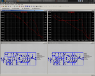
Here are two simulations. One uses your compensation and the other uses mine. Run the simulations as they are and compare FFT's, with mine high order harmonics are lower. I believe the reason for this is C7 (in attached schematics), which injects switching trash into the feedback loop.
Low order harmonics and THD increase, but higher order harmonics decrease.
In any case, if any connection between compensation and VAS output can be avoided, the same general thing will happen.
- keantoken
Low order harmonics and THD increase, but higher order harmonics decrease.
In any case, if any connection between compensation and VAS output can be avoided, the same general thing will happen.
- keantoken
Attachments
This is probably the case with real components as well, just not simulations or model faults. When I matched drivers for my Symasyms, I got the same result.The MJL15033/32 models have horribly mismatched Hfe, the 34/35 models are better,
- keantoken
With both 15032/15033 and 15030/15031 I got about 50-100% difference for Hfe, but with 15034/15035 they were within a couple of %.
The next thing to notice is the distortion at 100Hz. for my compensation scheme, 100Hz distortion is nearly nonexistant, because of the higher OLG BW. However, distortion for the traditional scheme is .00043%, nearly the same as for 1KHz. The OLG plots below will explain why.
- keantoken
- keantoken
Attachments
OS, how much have you thought about the Zobel? The L||R greatly improves stability into capacitive loads. However I believe 3.3uH is overkill. This is how I would adjust the zobel, for your consideration:
1: Pick a value of R that is the lowest load the amp is designed to perform into (or be stable into, to be more specific - for instance, some amps may have stability problems into low loads like .5 ohms). This resistor may be increased, but not decreased. Increasing it will increase any resonance between load capacitance and the inductor.
2: Add the maximum expected capacitive load, in parallel with a load equal to the zobel R, and adjust the inductor for no ringing.
This way we don't unwittingly choose a zobel that compromises sound quality, yet the circuit will be stable into electrostatics with minimal HF phase shift.
Using this I get a 560nH||2ohm zobel (guessing about R size) for a max 470nF load.
- keantoken
keen , you forgot the MJE15034/35 models , you might of included them in "mongrelmodels.txt" On other words, your .asc's don't run "out of the box".
edit: also , what are "sa1381/ sc3503" ?? Are these your models or andy C's , I also do not have them.
good note on the drivers, I will order 4 of each.
OS ARGGG!!
On other words, your .asc's don't run "out of the box".edit: also , what are "sa1381/ sc3503" ?? Are these your models or andy C's , I also do not have them.
good note on the drivers, I will order 4 of each.
OS ARGGG!!
Last edited:
- Status
- This old topic is closed. If you want to reopen this topic, contact a moderator using the "Report Post" button.
- Home
- Amplifiers
- Solid State
- The MONGREL (supersym II)