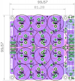
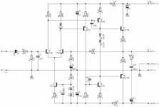
sch, gerbers and stuffing guide.
Although i/p terminals are shown to be 5mm pitch termi blocks, One could fit 6.35mmx 0.81mm faston connectors. There are some optional ground vias at the center and towards o/p side.
Regards
Prasi
Although i/p terminals are shown to be 5mm pitch termi blocks, One could fit 6.35mmx 0.81mm faston connectors. There are some optional ground vias at the center and towards o/p side.
Regards
Prasi
Attachments
Last edited:
sch, gerbers and stuffing guide.
Although i/p terminals are shown to be 5mm pitch termi blocks, One could fit 6.35mmx 0.81mm faston connectors. There are some optional ground vias at the center and towards o/p side.
Regards
Prasi
Great work Prasi. Thanks for sharing.
")
Great work Prasi. Thanks for sharing.
Merhaba, thanks. Do share here for the benefit of others if you build this cap bank.
Regards
Prasi
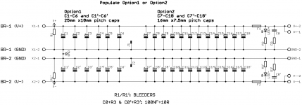
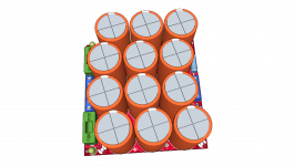
ok, this is how 25mm caps fit..
The second image shows where the resistors fit on the bottom (to be soldered first before putting caps and fuse holders.
PS, Orange colored caps are the omnipresent (in India) "Keltron Electrolytic Capacitors".
The second image shows where the resistors fit on the bottom (to be soldered first before putting caps and fuse holders.
PS, Orange colored caps are the omnipresent (in India) "Keltron Electrolytic Capacitors"
.Attachments
Last edited:
Merhaba, thanks. Do share here for the benefit of others if you build this cap bank.
Regards
Prasi
Merhaba [emoji112] Prasi
I ordered 5 pieces pcb from easyeda
I will post here after i finish it
Regards [emoji120]
sch, gerbers and stuffing guide.
Although i/p terminals are shown to be 5mm pitch termi blocks, One could fit 6.35mmx 0.81mm faston connectors. There are some optional ground vias at the center and towards o/p side.
Regards
Prasi
Nice work... you cun upgrade this pcb for PSU60 or PSU75
Regards
Prasi,
Forgive me in advance, as I am new to looking at schematics and visualizing the circuit board. My question is: " Does one need to still solder wire to connect the caps in parallel, or is there hidden traces in the pcb that connect the +, -, and Gnd as shown in the schematic.
Thanks for the help,
Myles
Hi Myles,
there is no need for any additional wire.
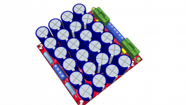
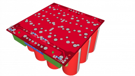
There are 2 top planes (of copper) that connect the caps' positive and negative pins.
There is a ground plane on the bottom that connects to all the ground pins of the electrolytic caps.
zoom in on the image of a single cap and you will see 4 blue spokes connecting cap pin (rail). 4 pink spokes connecting the cap's ground pin.
hope this clarifies the scheme.
I have provided thermal relief (4 spokes of PCB copper connecting the cap's pins) so that soldering is easier and can be done with an ordinary 25W iron available with most people.
there is no need for any additional wire.
There are 2 top planes (of copper) that connect the caps' positive and negative pins.
There is a ground plane on the bottom that connects to all the ground pins of the electrolytic caps.
zoom in on the image of a single cap and you will see 4 blue spokes connecting cap pin (rail). 4 pink spokes connecting the cap's ground pin.
hope this clarifies the scheme.
I have provided thermal relief (4 spokes of PCB copper connecting the cap's pins) so that soldering is easier and can be done with an ordinary 25W iron available with most people.
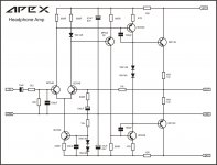
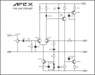
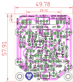
just a quick dirty little 'diy-friendly' layout of Mr. Mile's very flexible ckt.
It can be a pre-amp or a head amp .. (can also be FX-8 amp, but I havent given a thought to this).
First 2 images are Mr. Mile's designs and 3rd is a head amp layout and 4th is my exact schema.
regards
Prasi
It can be a pre-amp or a head amp .. (can also be FX-8 amp, but I havent given a thought to this).
First 2 images are Mr. Mile's designs and 3rd is a head amp layout and 4th is my exact schema.
regards
Prasi
Attachments
Nice work... you cun upgrade this pcb for PSU60 or PSU75
Regards
Thanks Mr. Mile, Upgrading it to PSU 60 /PSU75 will make PCB bigger and will no longer be $2 for 10 PCB +shipping.
Is it ok if we put the PSU 75 other components on another PCB of 100x 100, so that they can be mounted on top each other in the chasiss?
There are several Gerber files posted for FX8 (as well as many other amps). Send those Gerber files to one of the Chinese board houses and you can buy 10 for $2 plus $20 shipping via DHL to US. It may cost less to other countries. India is $8 for example. There is a thread called Index of Apex amps. The directory in that thread will give you links to locations of Gerbers. Many amps also have pdfs of copper traces and you can do your own etching at home.

Hi I want to make some of apex's amps for myself. Can I buy pcb's somewhere. Or can I get pdf's of the copper so I can etch myself? I have read through most of thread and may have misssed it. I like the fx8 and a few other small ones especially
Build the APEX FX-8 Bimo mod as reported by xrk and others.
Its already posted in thread , both gerbers, and diya pdf files. here
100W Ultimate Fidelity Amplifier
you can send the gerber zip file to any of the chinese board houses wihout facing any issues.
Schema here
100W Ultimate Fidelity Amplifier
bias procedure
Procedure for bias.
1. you will need 2 nos. of 10ohm 1W/2W resistors.
1a. turn the trim pot so that resistance between first and third leg of trimmer is approx 250 ohm.
2. Connect one lead these 10ohm resistors in series with your + and - rail wires of psu.
3. connect the other lead of resistors to amplifier +/- supply connector on amp pcb.
4. switch on supply and measure the voltage drop across these rail resistors.
4a. measure the voltage between spk out and ground. this is offset. it should be less than +/-30mV. Good matching of Hfe of i/p transistor pair (Q1/Q3) will ensure that offset is close to zero.
5. total quiescient current is given by I= V/10ohm
6. set the pot so that voltage drop across 10 ohm rail resistors is about 1V to 1.1 V.
7. Let the amp warm up for 1/2 an hour recheck the bias
8. Adjust pot if required to have voltage drop of 1 to 1.1 V.
9. This will ensure that you get a bias through o/p stage of approx. 100mA.
let me know, if you need anything else.

wonder who will be posting the 10,000th post, lucky him!
long live "100W Ultimate Fidelity Amplifier"
Hi I want to make some of apex's amps for myself. Can I buy pcb's somewhere. Or can I get pdf's of the copper so I can etch myself? I have read through most of thread and may have misssed it. I like the fx8 and a few other small ones especially
For the adventurous, the FX8 Bimo runs superbly at 1.2amp bias current and 24v rails for pure Class A up to 16wrms. That's what I am running now and it's great sounding. Winter is here and I don't mind having some extra heat in the lab to keep things comfy
100W Ultimate Fidelity Amplifier
Last edited:
Thanks for the reply, I am making a couple FH9 this morning since I found the PDF's from Sonal Kunal. Thank you Sonal for the hard work. And the rest of the group. This truly is a unique post. I am surprised its not in a separate forum. I will be sending off some gerbers soon. I am just making sure I send the correct ones. The directory of Apex is great! I will be posting my Apex amplifiers as soon as I get something interesting going here! One more makes 10,000!!!
- Home
- Amplifiers
- Solid State
- 100W Ultimate Fidelity Amplifier