I do not know if I am asking for too much but can You repeat one square wave measurement on 8 r with small cap in parallel please ( someting like 0,47uf or similar)
Thanks
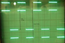
Here are the pictures (1 - 5 - 10 - 15 - 20 kHz).
regards Olaf
Attachments
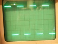
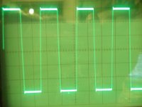
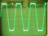
Sorry, forgotten - cap was 470nF.
regards
Thank You very very much.
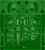
Amp looks rock solid construction. I am waiting for all parts arive to complete it.
Thanks again
post2041.
You really need to compare input signal to output signal using a dual beam or dual trace scope. (dual beam are quite rare).
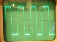
The input signal is a pure exactly square wave with 0.8V approx. as shown in Fig. with 1kHz.
The differences in output are the slope with increasing frequency, and the small peaks at the corners (see picture).
What else can we see, phase shift?
I can do it again if required. The oscilloscop is for dual-measuring.
regards Olaf
Attachments
Yes, you and we need to see the input signal to allow comparison with the output signal.
If the input has overshoot and this is mimicked in the output, but you don't show us the input, we could be mislead into thinking the amplifier is adding the overshoot.
You must be unbiased in how you present the information.
If the input has overshoot and this is mimicked in the output, but you don't show us the input, we could be mislead into thinking the amplifier is adding the overshoot.
You must be unbiased in how you present the information.
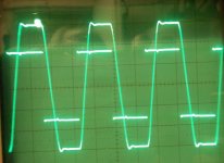
OK, here are the new images.
I hope someone will explain what can be seen in the pictures. I can measure again, today is holiday in Germany ;-)
Compared to the original circuit, I use 220R instead 180R in CCS.
regards Olaf
I hope someone will explain what can be seen in the pictures. I can measure again, today is holiday in Germany ;-)
Compared to the original circuit, I use 220R instead 180R in CCS.
regards Olaf
Attachments
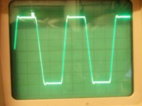
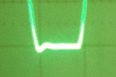
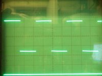
The input has a slightly rounded corner to the squarewave and no evidence of overshoot that I can see.
The output clearly shows overshoot and slew rate.
Are your probes adjusted to show squarewaves correctly?
This is input if Amp has no power. The peaks on input come from the amplifier.
Attachments
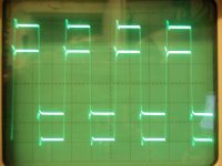
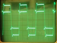
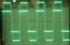
Now I changed all 330p to 100p. Slew rate is better as expected.
(10 + 20kHz). I hope, the probes are correct, but 20cm wire.
regards
Thank you for this measurements, result is very good.
Regards
This latest pic looks different from the previous input.
Have you swapped scope probes?
I ask again
Have you swapped scope probes?
I ask again
Are your probes adjusted to show squarewaves correctly?
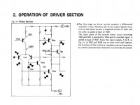
I like the Apex AX11, and this is not foreign to me because it is similar to the scheme Sansui AU217
Greetings Denmas.
Thanks for this info, yes it's same topology.
Regards
Attachments
- Home
- Amplifiers
- Solid State
- 100W Ultimate Fidelity Amplifier