Here it is, hot off the scanner. Message me if you'd like the pdf instead (these jpgs were exported from the pdf since it was too big to attach here).
Attachments
Last edited:
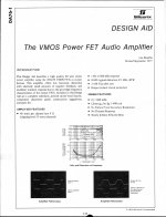
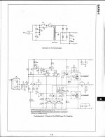
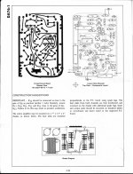
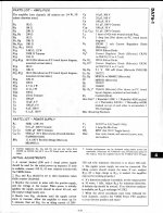
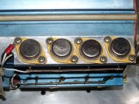
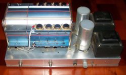
I built several of the audio amps ala Siliconix 1979 app note DA76-1. I still run the MOSfet amplifier today. Sounds as good as any tube amp even driving difficult complex loads such as Magnaplaners or full range electrostats. The 2N6658 are very linear and the Siliconix design used very little negative feedback. Closed loop BW was 800Khz. The extremely wide BW and very low negative feedback means this amp has the transparent sound quality of the best room heater tube amps. I used eight 2N6658 MOSFets instead of the twelve suggested by DA76-1. Here are a couple photo of my amplifier I built 30 years ago and still use.
http://i72.photobucket.com/albums/i163/miltons_stuff/MOSFetAudioAmp.jpg
http://i72.photobucket.com/albums/i163/miltons_stuff/2N6658MOSFets.jpg
http://i72.photobucket.com/albums/i163/miltons_stuff/MOSFetAudioAmp.jpg
http://i72.photobucket.com/albums/i163/miltons_stuff/2N6658MOSFets.jpg
Last edited:
I built several of the audio amps ala Siliconix 1979 app note DA76-1. I still run the MOSfet amplifier today. Sounds as good as any tube amp even driving difficult complex loads such as Magnaplaners or full range electrostats. The 2N6658 are very linear and the Siliconix design used very little negative feedback. Closed loop BW was 800Khz. The extremely wide BW and very low negative feedback means this amp has the transparent sound quality of the best room heater tube amps. I used eight 2N6658 MOSFets instead of the twelve suggested by DA76-1. Here are a couple photo of my amplifier I built 30 years ago and still use.
http://i72.photobucket.com/albums/i163/miltons_stuff/MOSFetAudioAmp.jpg
http://i72.photobucket.com/albums/i163/miltons_stuff/2N6658MOSFets.jpg
great work. About the ebay item number 120718818470 is to find such a project for very low price
Too pesimistic conclusion
This conclusion is wrong since it’s based on false assumption that transconductance of the output devices is constant 3S. A glimpse in BUZ21 dataseheet shows healthy 35A at Vgs= 2 x Vt.
Anyway, expecting a single pair of NMOS devices to drive 2Ohm load at full swing of +/- 42V is simply asking too much.
In my opinion the output stage in this topology should be very linear if driven in pure class A, better then complementary MOSFET A class. I wonder if somebody has tried it?
Chip
But wait a minute.
What is the maximum drive obtainable, then, at the gate, when there is an audio signal on top of the approx 2.7 V biasing DV voltage ? THERE is THE issue of conventional BUZamps. Due to the fact that the 2nd differential pair is biased by a current source, the maximum obtainable current is equal to the current source current. No more ! And this value, because of the differential principle, never exceeds TWICE the collector current that gets pushed at rest.
You see the issue ? The amp has an inherent current limitation. The swing on the NMOS gates cannot exceed a voltage that's the double of the threshold voltage ! The swing will be 0V (2nd differential collector shut-off) ... to 5.4V (2nd differential collector in saturation).
So, if the averaged transconductance of the NMOS equals to 3 Siemens (from threshold to decent current like 8 amp), the maximum current that will be delivered by the MOSFET is equal to 2.7V * 3 Siemens = 8 Amp roughly.
If the load is 4 Ohm, this is only 32 V. Discount some voltage losses in the driver, and you quickly come to the conclusion that a BUZamp (fitted with a single NMOS pair) will never be able to swing a 4 Ohm more than + and - 30V (60 Vpp), even if you have a high voltage power supply like + and - 45V.
It looks crazy, but it is true. If you want to see more inherent current limitation, put a 2 ohm load. Then you will see the open loop gain of the BUZmos amp trying to raise the NMOS gate voltages, but due to the saturation of the 2nd differential pair, you will measure a dumb 5.4 V max swing, no more, on the NMOS gates. And the same 8 amp on 2 ohm load is a ridiculous + and - 16V swing (only 32V pp). Irrespective of the open loop gain. And irrespective of the power supply rails that may be + and - 42V !
This conclusion is wrong since it’s based on false assumption that transconductance of the output devices is constant 3S. A glimpse in BUZ21 dataseheet shows healthy 35A at Vgs= 2 x Vt.
Anyway, expecting a single pair of NMOS devices to drive 2Ohm load at full swing of +/- 42V is simply asking too much.
In my opinion the output stage in this topology should be very linear if driven in pure class A, better then complementary MOSFET A class. I wonder if somebody has tried it?
Chip
Attachments
Pretty good news, this is indeed waking up my interest for such topology. Thanks !This conclusion is wrong since it’s based on false assumption that transconductance of the output devices is constant 3S. A glimpse in BUZ21 dataseheet shows healthy 35A at Vgs= 2 x Vt.
I built several of the audio amps ala Siliconix 1979 app note DA76-1. I still run the MOSfet amplifier today. Sounds as good as any tube amp even driving difficult complex loads such as Magnaplaners or full range electrostats. The 2N6658 are very linear and the Siliconix design used very little negative feedback. Closed loop BW was 800Khz. The extremely wide BW and very low negative feedback means this amp has the transparent sound quality of the best room heater tube amps. I used eight 2N6658 MOSFets instead of the twelve suggested by DA76-1. Here are a couple photo of my amplifier I built 30 years ago and still use.
http://i72.photobucket.com/albums/i163/miltons_stuff/MOSFetAudioAmp.jpg
http://i72.photobucket.com/albums/i163/miltons_stuff/2N6658MOSFets.jpg
Which of the mentioned MOSFETs by post #1 about
http://www.diyaudio.com/forums/soli...al-mosfets-class-ab-overview-p-spice-urls.htm
are close by the 2N6658 and its closely related Siliconix VN series ?
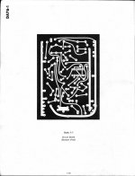
The pics from "photopucket" I have save here, because there the pics was often deleted after short time
Attachments
Last edited:
mosfet push-pull class A
In theory, MOSFET transfer function is supposed to follow the square law. Thus A class push-pull stage of two identical (well matched) devices should exhibit distortion-free operation (at least in theory). It takes good phase splitter to ensure proper counter-phase operation.
One implementation is the PLH amplifier (however Mr. Pass preferred somewhat asymmetrical operation). Buzamp and other amps shown in this thread use diff pair as phase splitter which is supposedly better at the task (especially if cascoded).
In reality MOSFET transfer curve deviates from the square law, so the distortion cancellation is not perfect. At higher frequencies non linear capacitance of the MOSFET contributes to further departure from ideal.
Anyway I’m considering this topology for low power class A amplifier. Linearity of the output stage will hopefully allow good performance with just mild to moderate global NFB. Therefore the gain of the input diff pair and phase splitter is not of primary concern but linearity and speed. On the other hand it’s not the best configuration for class AB operation.
I’m very interested to hear other’s experience if anybody has already tried class A of this topology, it would be very helpful if he/she shares the experience.
Chip
Sadly, to my knowledge there is nothing quite like the 2N6658 or equivalent amongst the current production MOSFETs. One possibility would be to look at Toshiba audio MOSFETs or Hitachi laterals but use them in class A as their treshold voltage is far too low for class AB implementation using this topology - since the voltage swing at the MOSFET gates is centered around the midpoint defined by half of the diff. driver stage tail current. This works very well for high treshold high gm MOSFETs because a 0V to 2x(treshold) swing is usually actually far more than is needed for full output.
With Hitachi laterals, for instance, Vgs required for maximum current is 8 times that of Vgs at around 100mA current. Assuming we want maximum Vgs from the driver to get us the maximum output current through the MOSFET (~7A), half of that being the quiscent state, puts the MOSFET bias current well into the ampere range. Not quite class A but the difference is negligible - one half of the PP output stage will be conducting around 6A current when the other half turns off. Of course, this may be just what is needed in a particular application")
However, since the max Vgs we are talking here is around 8-9V, the driver and preceeding stages need to have a higher positive supply than that of the output stage, for best output swing.
With Hitachi laterals, for instance, Vgs required for maximum current is 8 times that of Vgs at around 100mA current. Assuming we want maximum Vgs from the driver to get us the maximum output current through the MOSFET (~7A), half of that being the quiscent state, puts the MOSFET bias current well into the ampere range. Not quite class A but the difference is negligible - one half of the PP output stage will be conducting around 6A current when the other half turns off. Of course, this may be just what is needed in a particular application
However, since the max Vgs we are talking here is around 8-9V, the driver and preceeding stages need to have a higher positive supply than that of the output stage, for best output swing.
- Status
- This old topic is closed. If you want to reopen this topic, contact a moderator using the "Report Post" button.
- Home
- Amplifiers
- Solid State
- Siliconix & Siemens NMOS amplifiers