The Sansui Tanaka patent is US4401951. It also has the discussion of a few other "nonswitching" patents.
The common mistake with this approach is to leave Power stage with the new type of distortions due to unpredictable nonlinearity of P. transistors currents at the small levels (and near the signal zero crossing!).
orig posted by Steph_tsF:
This the famous Nelson Pass patent, indeed. Thanks 1000 times for reminding us. It is panicking to see those japanese companies (Matsushita, JVC, Pioneer, Sansui) rushing around 1978-1979 for Non-Switching Class AB, while Nelson Pass had it done as soon as Feb 1975, with his US patent granted Nov 1976.
here the link therefore and some others in this case:
Patent US4401951
Patent US6429744
Patent US5019789
Patent US6297699
Steph_tsF: I also had the same thought many times.
Last edited:
This was the simplified version of Pass' circuit from his patent.
At first glance, looks very similar to mine. But Pass' load isn't
forced to use only the diode path, so not sure how he keeps
a reactive load from sometimes depleting the emitter reserve?
Whatever else: even in simplest form, its more parts than I'd
ever throw at it. Still want to work up a sim of this one to see
if it might actually perform better in some subtle way I did not
expect???
I think crossing here is still shaped by the log law of emitters?
I'm not entirely sure yet if his quasi-complimetary diodes are
the primary shapers? I do see he sticks yet another diode into
parallel with some of his emitter resistance in Fig 5. Maybe to
do some shaping? Would have been redundant in my scheme...
Attachments
Last edited:
let's try a summary about the class AB Non-Switching, or class B Non-Switching output stages for Audio Power Amplifiers. We are not including any class AA or class A+ here.
Patents :
Technics New Class A :
JVC Super-A : US4274059
Pioneer Non-Switching : US4215318 and US4254379
Sansui Non-Switching : US4401951
We need to add :
Hitachi Superlinear : US4345215
Pass Non-Switching: US3995228
Dodson Hyperbolic Class A :
Thornton Non-Switching : US4160216
Hawksford Non-Switching :
All patents are downloadable from Patent Searching and Inventing Resources
AES preprints and papers :
Technics New Class A :
JVC Super-A :
Pioneer Non-Switching : AES E-Library: Non-Switching Amplifier
Sansui Non-Switching : AES E-Library: New Biasing Circuit for Class-B Operation
Sansui Non-Switching : AES E-Library: New Biasing Circuit for Class B Operation
Hitachi Superlinear :
Pass Non-Switching:
Dodson Hyperbolic Class A : AES E-Library: Quasi-Class A/Improved Class AB Bias Loop
Thornton Non-Switching : AES E-Library: A Power Class A Technique with Open Loop Stability
Hawksford Non-Switching : AES E-Library: Error Correction and Non-Switching Power Amplifier Output Stages
All AES papers are downloadable (subscription needed) from AES E-Library
Commercial products :
Technics New Class A : SU-V5 SU-V7 SU-V8 SU-V9
JVC Super-A : AX1 AX2 AX3 AX4 AX7
Pioneer Non-Switching : SA7800 SA8800 SA9800 A5 A6 A8 A9 A60 A70 A80
Sansui Non-Switching : AU-D5
Hitachi Superlinear : HA-3700 / HA-4700 (BJTs) and HA-7500 MK2 (MOSFETs)
Pass Non-Switching:
Dodson Hyperbolic Class A :
Thornton Non-Switching :
Hawksford Non-Switching :
Many service manuals are downloadable from Free Manuals User / Service / Schematics for Download | HiFi Engine
Any omission ?
I have not included some techniques used inside opamps (Burr-Brown, Texas Instruments), barely applicable to Audio Power Amplifiers.
Cheers,
Steph
Last edited:
Yes, like i mentioned, the very early Technics "hi end" power amplifiers used a class B amplifier to drive a low voltage full current class A output stageAny omission ?
Cheers,
Steph
") Here is an example, the SE-A1, if i remember correctly these things cost many thousands of ££££. Looks like they call it Class A+.
Here is an example, the SE-A1, if i remember correctly these things cost many thousands of ££££. Looks like they call it Class A+.They don't make them like they used to
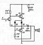
Can somebody derive a stronger version, powered by +42V/-42V and able to deal with 5 amps ? How should we name this, if we succeed ?I will show one "well forgotten" circuit from the '60s with the interesting properties. It is SRPP (in Cl. A bias), but is Non-Switching in Cl. AB bias. T11 will never switch off. The Non-switching condition for T12 is V(D5)≥0.5V + V(D6)max. D6 should be Schottky (to minimize power waste) with the appropriate current rating and in TO-220 or TO-3P case. Obviously, it is the voltage follower/power buffer and T1 provides the Error Correction function for Pushing and Pulling action of T11, T12. The bias with the shown values: T1, T12 ~0.4 mA, T11 ~10 mA, D6 is (may be) non conducting. D5 is generally not necessary (only for non-switching T12 and Cl. A bias) and can be shorted. C61 provides bootstrapping for R59.
Attachments
I know. Class A+ and class AA are expensive solutions, with two separate amplifiers for each channel. Over time, the class A+ got replaced by the class AA, where the second amplifier is a total feedback current buffer. You may consider the class AA as an upgraded Quad 405, still with a balancing bridge, but this time it is wideband (four resistors) and there is a total local feedback around the current dumper, which is a dedicated amp with a big open loop gain, instead of a dumb darlington. I think I'll open a few separate threads about Hitachi Dynharmony class G, Technics and Pioneer class A+, Technics class AA, QSC floating supply bridge. This present thread is about fiddling with the Vbe multiplier. Okay, the Thornton scheme is not what we may call a Vbe multiplier fidle, but as the Technics New Class A was already there, I found a nice parallelism between Technics New Class A, and Thornton scheme. They both displace the problem, using fast diodes. All classifications have limitations.The very early Technics "hi end" power amplifiers used a class B amplifier to drive a low voltage full current class A output stage
Cheers,
Steph
No problem Steph I just thought i'd mention it for completeness & the fact that it had a true class A output stage.
Besides sooner or later (depending on how long it takes me to get stuff together) i'll be building a few of similar design 250W+ RMS 8ohm & 500W+ RMS 4ohm. There's plenty to go about
I just thought i'd mention it for completeness & the fact that it had a true class A output stage.Besides sooner or later (depending on how long it takes me to get stuff together) i'll be building a few of similar design 250W+ RMS 8ohm & 500W+ RMS 4ohm. There's plenty to go about
Thanks for the info. Attached there is a .txt file containing the upgraded info.Trio-Kenwood pat. US4342966.
Attachments
Last edited:
I don't have AES access, but I've reviewed the patent numbers
given so far, and don't yet see an overlap with the circuit I am
proposing.
The Thornton Patent 4160216 uses diodes for commutation, and
all output currents must flow through those diodes, thus output
can't source or steal away the reserve current set by either CCS.
Only this much prior art seems at all similar to what I'm thinking..
From here, we see that I simplify to a single resistor as a current
source. But more importantly, we see that Diode curves control
the crossing shape, and power device curve is almost irrelevant.
Thorton's emitters participate in series with his diodes to shape
his crossing. My emitters (IF BJT are used here) don't.
Underbias voltage across the diode stack is held to a constant.
And bias voltage across power devices is not held to a constant,
but slave to whatever satisfies the diode stack rule. Nothing in
Thorton's patent goes quite this far.
Thats weird, and unique, and not prior art. And IF it turns out that
nobody else holds patent before I published to this public domain,
then its gonna be real hard for them to pull the rug out from under
our right to use it. And I am giving right now my written permission
to everyone: use this any way you want, commercial or whatever.
Thats a big "IF", cause there may be patents I don't know about.
Until we know, I may not have any rights to give that permission.
My input stage is weird enough, I highly doubt its covered either.
but someone ought to check to be sure, before you build for profit.
The soft current limiter is Keantoken's idea. I don't know if he's in
the loop on this thread yet or not?
Last edited:
Member
Joined 2009
Paid Member
How sensitive is it to device - device variations ?
Like I said: let cold Schottkys do the thinking, not hot power devices.
Exactly the reason I don't think any of the patents above could apply.
They still depend on "complimentary" power devices, I don't.
Exactly the same sim as before, except: BiPolar PNP sub'd for P-CH...
Only the two Schottkys really have to match...
Attachments
I the idle current on the input transistors so low that high input impedance is asured ?
What? No.. Impedance is actually kinda low. About 7.5K looking into the input.
I was only shooting for an extreme low offset, and no patent infringements...
You are driving through emitters, you will see both 47Ks on the collector ends.
The first tansistor is transparent. Its the next transistor the real one you are
driving. But this trick makes it look like a depletion mode device of very very
predictable threshold. Though input impedance surely not its strongest merit.
Sure, you can sub conventional complimentary LTPs, might work even better.
But then you right back in the land of ordinary, and maybe even infringing???
Input stages are a quagmire of inspiration stifling old patents too... You really
want to open that can of worms?
I could Muntz this down till it looks like Zen + Aleph and a pair of diodes...
But what fun would that be? And then would Nelson let you sell it?
Last edited:
Member
Joined 2009
Paid Member
There are a zillion patents out there, many of them useless. I'm not sure why you are so concerned about this, it's DIY afterall. Surely, unless you are flagrantly asking for trouble by making a clone device it's often not worth the expense for somebody to come after you for some old obscure patent unless you have a significant level of sales revenue for them to take a slice out of ?
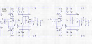
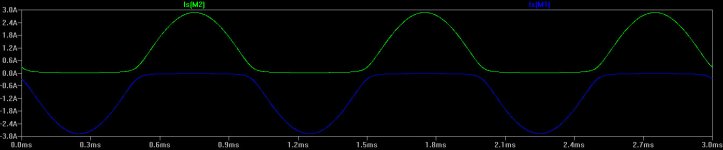
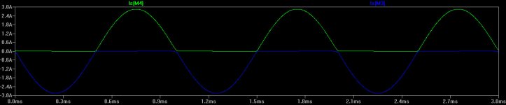
here is a test bench under LTspiceIV about kenpeter class AB Soft Non-Switching showing excellent results. See the .zip file. The idle current is about 300mA. How to reduce it ?
Attachments
Built 20 such independend devices for +/-42V, each with choosed idle current of 250mA. Then connect the devices parallel through decoupling resistors.steph_tsf; from post #25 - go also to post #15 2149213 said:Can somebody derive a stronger version, powered by +42V/-42V and able to deal with 5 amps ? How should we name this, if we succeed ?
For paralleling the output transistors directly a great amount of time for selecting and matching to similare values of Hfe and Ube voltage is necessary. Also the requirements for the driver are too large. Therefore I don't like this.
Perhaps the right name could be DOZ-II (Death of Zen, Var II) because the great similarity to this circuit (what Mr. Nelson Pass certainly will be very pleased).
Death of Zen - A new Class-A power amp
Here the emitter of driver transistor drives the base of the lower transistor directly, while in this circuit the driving there comes from the output (via the diode).
Last edited:
错误
你的线路做对了一半,实际工作时会很难控制静态电流,也会将q5损坏。
like i said: Let cold schottkys do the thinking, not hot power devices.
Exactly the reason i don't think any of the patents above could apply.
They still depend on "complimentary" power devices, i don't.
Exactly the same sim as before, except: Bipolar pnp sub'd for p-ch...
Only the two schottkys really have to match...
你的线路做对了一半,实际工作时会很难控制静态电流,也会将q5损坏。
- Status
- This old topic is closed. If you want to reopen this topic, contact a moderator using the "Report Post" button.
- Home
- Amplifiers
- Solid State
- New Class A, Super-A, Non-Switching : need a revival ?