Hi Havenwood,
interesting amplifier you dug up. It's always nice to see the many engineering advances made over time. The Denon is claimed to be a non-feedback design. This is not the same as a non-switching design.. Both technologies may help to arrive at a 'perfect' amplifier, but the approach is much different: non-switching ideally prevents cross-over distortion (when the output goes from + to - or from - to +) while non feedback variety prevents the multitude of intermodulation and harmonic distortions that can surface with limited amounts of negative feedback applied in an amplifier. Often less FeedBack can be applied than desired because of limitation in real world components the amp is build with.
regards, Mark
早在一年前这线路做成功了,现在已经获得中国专利。你这线路含有专利的一部分。
He said they had made this type of schematic in china and Chinese got the pattern for this type of design.what means this exactly?
For what it's worth, I rather like the class-AB bias loop principle that the Electronics Instrumentation group of the Delft University has used since 1976. Basically you sense the output currents of the output devices, pass them through a non-linear network and increase or decrease the current through both devices until the output of the non-linear network matches some set value. The non-linear network is typically some smooth approximation of a minimum selector.
I used this technique in 1994 to build a non-switching, adjustment-free amplifier with cheap BUZ10 output transistors - which appealed to me a lot because I didn't have much money back then. The LT1166 is another example of this technique, as is the Circlophone on this forum.
I haven't a clue whether the distortion figures are larger or smaller than with a more conventional amplifier, nor do I care - worrying about specifications sounds like work to me rather than like hobby.
so, what is the way to lower crossover dostortion low biased AB output stages?
")
As long as your transistors are bias on properly, about 10ma-20ma per transistor is more than enough. Some amps would even cope with just 1mA per transistor without hearing and cross over.
Most important is to have good schematic for sound quality.
Good implementation is even more important.Most important is to have good schematic for sound quality.
For what it's worth, I rather like the class-AB bias loop principle that the Electronics Instrumentation group of the Delft University has used since 1976.
Link ?
Good implementation is even more important.
from my exprience I have clone m9as2, tried putting it on class a, vs class ab. Sound quality wise very similar to operating at class b.
Added regulator vs without regulator for clone, no diffrence heard.
However with very high quality schematics that I had designed. All the diffrence can be heard from regulating and class b to a.
The clone and other so call high quality schematics they sell is so poor that I'd listen to nothing instead.
Link ?
Monolithic operational amplifier with improved HF behavior
Johan H. Huijsing and Frans Tol
1976
http://ieeexplore.ieee.org/iel5/4/22547/01050722.pdf
and many other articles with Johan H. Huijsing as co-author.
My amplifier was published in Electronics World in 1996, February 1996 I think, in an article called "Audio power with a new loop".
I later figured out you can use the same technique for an amplifier with user-set bias that indicates whether it works in class A or not, see
Amplifier with variable bias that indicates whether it works in A or AB
Amplifier with variable bias that indicates whether it works in A or AB
Monolithic operational amplifier design with improved HF behaviour
J.H. Huijsing ; F. Tol
All-NPN output stages were popular in April 1976 when this was published, but modern fabrication processes include acceptable PNPs, and modern opamps now employ PNPs in their output stage.
The mysterious node "S" that appears throughout Johan Huijising's schematic, is circled in red in the bottom right corner. Click on the white X shaped icon in the lower left corner, to see the image fullsize without compression distortions.
_
J.H. Huijsing ; F. Tol
Abstract:
The design of a monolithic operational amplifier, which combines a large bandwidth and a high output current, is described. The output stage is equipped with n-p-n transistors only, biased in class-AB by an internal common-mode feedback loop. The intermediate stage consists of a unity-current-gain split-frequency-band voltage level shift. An integrated version, intended for driving 50-/spl Omega/ coaxial line systems, achieves a bandwidth of 25 MHz and 100-mA output current. The principle described provides the possibility for achieving higher output currents.
The design of a monolithic operational amplifier, which combines a large bandwidth and a high output current, is described. The output stage is equipped with n-p-n transistors only, biased in class-AB by an internal common-mode feedback loop. The intermediate stage consists of a unity-current-gain split-frequency-band voltage level shift. An integrated version, intended for driving 50-/spl Omega/ coaxial line systems, achieves a bandwidth of 25 MHz and 100-mA output current. The principle described provides the possibility for achieving higher output currents.
All-NPN output stages were popular in April 1976 when this was published, but modern fabrication processes include acceptable PNPs, and modern opamps now employ PNPs in their output stage.
The mysterious node "S" that appears throughout Johan Huijising's schematic, is circled in red in the bottom right corner. Click on the white X shaped icon in the lower left corner, to see the image fullsize without compression distortions.
_
Attachments
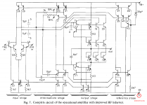
Probably S stands for the P-type substrate that needs to be connected to the negative supply to keep all transistors isolated from each other.
The interesting bit is that the class-AB biasing is handled by the non-linear common-mode loop rather than by the output devices themselves. This makes it independent of temperature variations of the output devices and it allows one to use output stages that are not voltage followers - such as the combined common-collector/common-emitter stage used by Johan H. Huijsing and Frans Tol or a complete common-emitter (or common-source or common-cathode) stage.
By using a different non-linear network you can also implement whatever control law you want to have. I used an exp(-I1*R) + exp(-I2*R) = constant type of law for my non-switching amplifier.
- Status
- This old topic is closed. If you want to reopen this topic, contact a moderator using the "Report Post" button.
- Home
- Amplifiers
- Solid State
- New Class A, Super-A, Non-Switching : need a revival ?