The spectrum of harmonics of a quasi complementary is considered more musical.
Imo the foremost issue is oscillation I wonder why no rf burnout had ever occurred to the
2N3055 as these should show second order crossover if there is switching indeed.
It could be worth a try to replace the 2S... with the 2N3055 model in the sim.
Imo the foremost issue is oscillation I wonder why no rf burnout had ever occurred to the
2N3055 as these should show second order crossover if there is switching indeed.
It could be worth a try to replace the 2S... with the 2N3055 model in the sim.
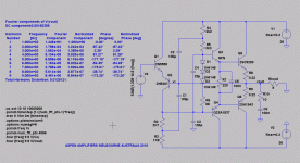
Complementary Class AB Power Buffer
Here is the power buffer rearranged for complementary output drive.
The Rush Cascode input stage doubles as the VAS and uses shunt compensation since there are no phase reversals through the signal path. The twin bootstraps and input offset set DC operating points. FR is very good, flat to almost a MHz. Distortion is passable, not wonderful, but this would sound pretty nice I believe.
Quiescent is around 70mA as designed. RC current varies between 220uA and 2.7mA. This causes variations in Vbe at Q1 and Q2 which contributes to distortion but it's largely H2, which at 30Vp (56 watts into 8R) is around 65dB below the fundamental.
If someone decides to build this I'd be interested to hear from them. Of course, it goes without saying this would need a tube or other voltage amplifier in front of it; Zin is suitably high, many tens of kilohms.
Hugh
Attachments
Hahfran,
There is no oscillation if all 1K resistors remain as is, no change, though with 2SC5200, modern output devices.
More to follow,
Hugh
Ok I will sooner or later make one however the quasi version. I have eventually managed to open the case of the amp. The devices Tr1, Tr4 of the original schematic are BD1.. types in SOT package mounted in thermal contact with the heatsink. This could have been an advice in the lost original article in Wirless world. For the intended use, drivers in active speakers, thermal stability is an important issue.
The 2SA1837 are not available I have a bunch of 2SA968
Hi Hugh,
Twin bootstraps remind me this 1970 circuit by Linsley-Hood (source : Goeff Moos's Class A amplifier site).
Twin bootstraps remind me this 1970 circuit by Linsley-Hood (source : Goeff Moos's Class A amplifier site).
An externally hosted image should be here but it was not working when we last tested it.
Whats up, guys ??
Well, I don't know.
Without somebody building a prototype (shouldn't be that hard given that it's a rather simple amp) and doing some measurements, there is not much to talk about. Sims for such low THD-amps are nice, but generally not really reliable.
And all this talk about distortion profiles and the likes makes me smile given how the distortion spectra of popular drivers in modern speakers look like - and that they are easily a factor 10 larger
")
But that shouldn't stop anyone to contribute, of course.
Have fun, Hannes
Not correct in terms of sonic impression- that is what matters, after all.
Speakers may produce 10% h2 but as long the voice coil is in the almost linear range h3 is
very small. Crossover distortion has a very nasty spectrum if that sums up to thd 0,5%
it sounds much worse than a speaker's 10% h2. For ex. - although that makes no sense at all- a cello produces about 60% h2...that makes a cello a cello. The harmonics spectrum and the rise rate of the harmonics is characteristic like a fingerprint for every acoustical instrument and varies, too, with the artist's style. 10% more h2 is inaudible.
10% more h2 is inaudible.
Sure, I know that from the tube guys already. Craving for power the limit of inaudible distortion is set pretty high. I think it will be hard to find many people that believe that more than 1% H2 is inaudible.
But, well, I really don't care.
If this is your mantra, be it so.
See it positively, you can easily build a single ended Class A amp and be happy as it fulfills all your requirements. Avoid all distortion cancellation possibilities like push-pull or differential pairs as that will mess up your distortion profile (H3 dominant then).
Have fun, Hannes
PS: most drivers don't produce 10%H2 and 'very small' H3. Ususally H2 and H3 are pretty close, and maybe 15-20dB lower the higher orders.
Zaph|Audio
In loudspeakers, 1% (-40dB) is a typical figure both for H2 and H3 at moderate SPL. Crank it up a bit more and H2 and H3 will rise to 3% (-30dB).
Horns may be 10dB better easily.
Most amplifiers are another 30dB better (too good to care )
Warning: Performing speaker THD measurements may result in permanent changes in your point of view about amplifier THD
Horns may be 10dB better easily.
Most amplifiers are another 30dB better (too good to care
)Warning: Performing speaker THD measurements may result in permanent changes in your point of view about amplifier THD
Last edited:
The H3 will be already present. H2 and H4 would have to be intentionally added since the usual ideal modulators have little chances to produce them. A slight mismatch between high and low side switching timings and layouts may be enough for even harmonic production (by output impedance mismatch between sinking and sourcing current, as in class AB).
One thing that I have in mind is a self biasing n-channel MOSFET output stage based in this rush cascode approach.
One thing that I have in mind is a self biasing n-channel MOSFET output stage based in this rush cascode approach.
Last edited:
Hugh;
very nice circuit you have come up with - I built a similar design that was described on the 4Square website many years ago and found it to be a most suitable guitar amplifier.
It is the only design I have tried that clips gracefully and shows no "sticking" tendency.
Mine used bog standard BD139/BD140 2N3055/MJ2955 and I cannot remember what happened to it, or why I have completely forgotten about the Rush cascode ...
In loudspeakers, 1% (-40dB) is a typical figure both for H2 and H3 at moderate SPL. Crank it up a bit more and H2 and H3 will rise to 3% (-30dB).
Horns may be 10dB better easily.
Most amplifiers are another 30dB better (too good to care
Warning: Performing speaker THD measurements may result in permanent changes in your point of view about amplifier THD
Sounds convincing but is wrong. The objective measurement does not allow to predict the subjective impression. For example, no one - except musicians - hear the difference tones ( i.e. a Doppler effect) that is produced when a
bass-midrange reproduces a 1 khz signal and a 50 hz signal, the latter with max cone excursion. The 1 khz is frequency modulated by the 50 hz cone motion towards or away from the listener and that is by analysis a non harmonic distortion however composed of harmonics.
What one actually auditively perceives as distorted is not determined by the absolute amplitude of harmonics.
For example:
PhysOrg.com) -- New research shows our brains are a lot more chaotic than previously thought, and that this might be a good thing. Neurobiologists at the University of Maryland have discovered information about how the brain processes sound that challenges previous understandings of the auditory cortex, which had suggested an organization based on precise neuronal maps.
Informally speaking the brain computes from the signals from the auditive sense nerve what you prefer to hear. There is a second mechanism which is very sensitive to fast transients. It is this genetical heritage of predators
that makes transient distortions , switching distortions ( i.e. also time errors ) very unpleasant to us contemporary listeners although their relative amplitude could be in the -80 dB range.
Distortion is apparently the only thing we can go by, yet it is problematic since two amps with identical THD are not guaranteed to sound the same. There is something else to it; either the single tone tests routinely used do not correlate well with music, or the psychoacoustics are more complex than thought (as Hahfran alludes above), or both. THD is useful, perhaps, but not definitive, topology still seems to hold the key to the X-factor. The amp should not be considered simply an engineering problem; together with the source and the speakers it is a man-machine interface and the perceptual issues of human hearing likely have more influence than we think.
Most people tacitly agree with this, since the final question is always, 'How does it sound?' Even the rusted on THD proponents are concerned about 'how it sounds'. Therefore, we must build as well as theorize and try to keep an open mind.
There are very few push pull output stages which will output more than 97% (without feedback) of the input amplitude. This rapidly worsens if we use large emitter resistors to gain bias stability. Thus a 30Vp input signal seldom rises above 29Vp at the output due to Vbe creep and voltage drops in the emitter resistors, and while this is largely corrected by the nfb loop, the output suffers large signal distortion. This circuit is pretty good at 99.7%, because it uses nfb within itself courtesy of the single ended RC. Moreover it has very low Zout (simulated at 18 milliohms, consistent with the large nfb used, but likely about double this in practice) which obviates any need for global feedback encompassing the input voltage gain section.
Balaboo, thanks for your observations. Like most circuits, this is a hotch potch of different ideas thrown together, but it is unusual and it peforms well. It does seem to have a lot of phase shift, which may not be good, however. Neither does it handle loads less than 8R well because of negative half cycle current limiting, but that could be fixed with a pre-driver. I measure loop gain at almost 67dB; this explains why it is good. It is NOT a conventional feedforward circuit, although it does enjoy a lot of negative feedback.
I have not built it yet. I'm hoping someone else here may do that.
Hugh
Last edited:
Hahfran,
Replace the three diodes and resistor with a simple npn BD139 Vbe multiplier, mounted atop one of the output devices. Use 1k5 from collector to base, and around 1k trimpot from base to emitter. Use a 22uF cap across collector emitter; believe me, this will stop thermal runaway.
If you wish, you can also reduce loop gain by inserting a 22R resistor between the two emitters of the RC. This could also be useful.
Cheers,
Hugh
strange amp...
it has none of the advantage of current feed back topology,
as well as none of those of differential inputs,
despite mimicking the two...
in respect to hugh s schematic, Q1/Q2 can be seen as a
differential, no matter that the two transistors
are complementary...
feedback is returned to the base of the second stage,
making this amp a voltage feedback one...
the difference with a classic differential is that Q2
has no other current limiting that the one provided by the
collector s resistor s network...
anyway, Q2 s current is highly variable, thus creating lots
of distorsion if the available feeback is not high enough..
i think that it s an inferior design compared to the classical
current feedback design using the same number of active devices..
this latter was largely documented in some motorola s ap notes,
and is capable of -100 db distorsion at 10KHZ, with monotonic
deacrease of harmonic products..
for useful lectures, here again a link to rod s excellent description
of the thing....
Simple 60 Watt Power Amplifier
- Status
- This old topic is closed. If you want to reopen this topic, contact a moderator using the "Report Post" button.
- Home
- Amplifiers
- Solid State
- Class B w/o crossover distortion (1975)