I'm still at it ... trying for more power , better devices , and keeping it simple and reliable. While reading a little Douglas self (amp handbook), I ran across this statement :
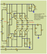
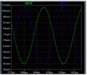
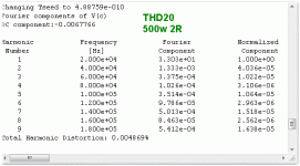
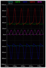
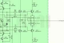
This seemed to deserve more investigation , and the best test was my new triple using njw0281/0302's (drivers) - njw21193/4's (outputs). The 21193/4's have HUGE dies (hefty Cob) , lower gain/Ft and killer SOA. After I plugged in the models for the 21193/4's , I noticed more Xover distortion even as I was driving them with smaller OP's. I then tried the type 3 driver config (1st attachment). This seemed to run most nicely in class A (attachment 2) , and to my surprise halved my THD20 ,plus reduced (considerably), the Xover artifacts being fed back via NFB.
This also brought up the question of model quality as the NJW21193/4's are newer to-3p ON devices and the models, (like the fairchild KSA's) seem to show the device in great detail (Cob , saturation "effects") versus "stupid" models - (mje340/50).
It was cool that the simulation showed what Mr. self predicted ,..smoother Xover from 10k up , rounded corners in the Xover region at HF ,and a nice class A driver region (70ma average).
Has anyone built something similar ??? I'd love to hear about it .
OS
BTW , WOW... what a improvement in the forum !!!
"type 3 is as equally good as type 2 at reverse biasing the output bases, and may give even better HF turnoff as the carriers are "swept" away by a higher resistance connected to a higher voltage" "this remains to be determined..."
This seemed to deserve more investigation , and the best test was my new triple using njw0281/0302's (drivers) - njw21193/4's (outputs). The 21193/4's have HUGE dies (hefty Cob) , lower gain/Ft and killer SOA. After I plugged in the models for the 21193/4's , I noticed more Xover distortion even as I was driving them with smaller OP's. I then tried the type 3 driver config (1st attachment). This seemed to run most nicely in class A (attachment 2) , and to my surprise halved my THD20 ,plus reduced (considerably), the Xover artifacts being fed back via NFB.
This also brought up the question of model quality as the NJW21193/4's are newer to-3p ON devices and the models, (like the fairchild KSA's) seem to show the device in great detail (Cob , saturation "effects") versus "stupid" models - (mje340/50).
It was cool that the simulation showed what Mr. self predicted ,..smoother Xover from 10k up , rounded corners in the Xover region at HF ,and a nice class A driver region (70ma average).
Has anyone built something similar ??? I'd love to hear about it .
OS
BTW , WOW... what a improvement in the forum !!!
Attachments
Hi Os
That looks like a triple with the driver stage biased to the rails. It does show improved figures, scheme used by electrocompaniet and some others. Electrocompaniet goes further and uses a current source instead of resistors to bias which improves things further if youd like to try. Adreia Scafolli a Italian designer goes even further and biases the predrivers like that too, all show improvements THD wise, as for the sound youd have to try and listen to the sound of these schemes. The one you showed but using current sources gives a mighty kick in the bass but your amp better be quite fast or the bass will overwhelm. Carlos the destroyer didnt like it, I found no problems with it except the rest of the amp should be fast or the mids will sound slightly muddled.
That looks like a triple with the driver stage biased to the rails. It does show improved figures, scheme used by electrocompaniet and some others. Electrocompaniet goes further and uses a current source instead of resistors to bias which improves things further if youd like to try. Adreia Scafolli a Italian designer goes even further and biases the predrivers like that too, all show improvements THD wise, as for the sound youd have to try and listen to the sound of these schemes. The one you showed but using current sources gives a mighty kick in the bass but your amp better be quite fast or the bass will overwhelm. Carlos the destroyer didnt like it, I found no problems with it except the rest of the amp should be fast or the mids will sound slightly muddled.


Carlos the destroyer didnt like it/QUOTE]
That is a good sign !!
scheme used by electrocompaniet and some others. Electrocompaniet goes further and uses a current source instead of resistors to bias which improves things further if youd like to try. Adreia Scafolli a Italian designer goes even further and biases the predrivers like that too, all show improvements THD wise,
Ahhh, others have tried it... must check that out!
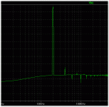
The FFT (attachment 1)shows the H3-7 almost goes away , even at full throttle. This looks a little like a diamond buffer in theory. I must say besides the already mentioned effects , the type 3 triple is far more stable as well.
OS
Attachments
Theres plenty one can do with output stages to improve the figures, use current mirrors instead of 2 current sources to get the currents in the collectors very close and it will show further improvement or even better use the current mirors but change the drivers to cfp s, I couldnt get this stable with BJTs but with mosfets it works great.
This looks a little like a diamond buffer in theory...
OS
This topology is much better than DB where a CCS limited driver current is available for driving the output BJTs
Last edited:
... even better use the current mirors but change the drivers to cfp s, I couldnt get this stable with BJTs but with mosfets it works great.
I was able to get this run stable, CFP drivers loaded by CCSs from opposite rail, and it sound very very good! The only downside is the complexity and the thermal dissipation from drivers and CCSs, because you need at least 100mA through each driver to run stable!
From my POV, this is the almost perfect class B output stage, as per Self OPS class definition.
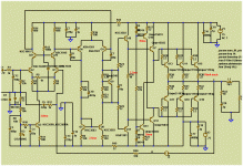
Is this what you guys meant ??? (attachment 1)
In a non-CFP mode (EF) , I ran at 35ma with great results. Perhaps the CFP ,with local FB , contributed to this instability. As far as complexity and extra dissipation .. 2 more mje15032/33 drivers and 4 diodes is not bad !! 140ma extra current would be "swamped out" by the 4+ pairs of beasty 21193/4's.
It is looking a little more "krill - ish".. BTW , at least in simulation , the CCS's dropped the THD20 in half again ...

OS
Edit : I thought it out , I could still use my 0281/0302's as the actual drivers, while using the mje's as separately heatsinked CCS's. That would make the CCS's independent of the main EF's Vbe..
Roender - The only downside is the complexity and the thermal dissipation from drivers and CCSs, because you need at least 100mA through each driver to run stable!
In a non-CFP mode (EF) , I ran at 35ma with great results. Perhaps the CFP ,with local FB , contributed to this instability. As far as complexity and extra dissipation .. 2 more mje15032/33 drivers and 4 diodes is not bad !! 140ma extra current would be "swamped out" by the 4+ pairs of beasty 21193/4's.
Roender - This topology is much better than DB where a CCS limited driver current is available for driving the output BJTs
It is looking a little more "krill - ish"..


OS
Edit : I thought it out , I could still use my 0281/0302's as the actual drivers, while using the mje's as separately heatsinked CCS's. That would make the CCS's independent of the main EF's Vbe..
Attachments
Last edited:
by raphael - I tried this topology "rail-to-rail", problem is requiring much current, you check Ib of output TRs, After you compare with Ib drivers.
does not seem too bad ,If you use "fat" drivers (outputs... njw0281/0302)
at 4r /400w (see attachment 1) , the CCS's (green/light blue) are steady at 35ma +-2ma -the mje15032/33's with a small PCB 10watt/c heatsink would be slightly warm at most (happy ,cool transistors).
The drivers Ie (combined Ib of all outputs - Red/blue) is much higher , with a minimum 30ma ..peaking to 88ma. The drivers are outputs and will be on the same heatsink as the main outputs so this is not a real issue.
(pink/grey) is just the current (Ib )to one pair of outputs. The THD improvement (attachment 2)is the best I've seen at 4R and even holds at 2R !! No wonder the Electrocompaniet amps have such high damping factors !!
At these levels , a standard type 2 EF will drop dead (beta droop)...
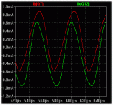
The Ib of the drivers is (attachment 3) is less than 1ma , no sweat for the ksa's (predrivers) ,no heatsinking would be required.
OS
OS
Attachments
ostripper,
roender,
Yes, it gives you 3 (hybrid triple) bastantly nonlinear base-emitter junctions.Self type 3 EF (hybrid triple)... any pointers ??
roender,
I cannot agree on that for a second.This topology is much better than DB where a CCS limited driver current is available for driving the output BJTs.
Yes, it gives you 3 (hybrid triple) bastantly nonlinear base-emitter junctions.
Elaborate ??? (google/wiki says bastantly is NOT a word)
To make a statement and not explain why is counter-productive.
I cannot agree on that for a second.
But why ?? point proven..
Andy C . , over in the YAP thread , has the .asc to compare the T2 EF to the DB , I will sub this OP for the EF and then we will see
which is more linear in isolation ...
OS
Last edited:
does not seem too bad ,If you use "fat" drivers (outputs... njw0281/0302)
at 4r /400w (see attachment 1) , the CCS's (green/light blue) are steady at 35ma +-2ma -the mje15032/33's with a small PCB 10watt/c heatsink would be slightly warm at most (happy ,cool transistors).
The drivers Ie (combined Ib of all outputs - Red/blue) is much higher , with a minimum 30ma ..peaking to 88ma. The drivers are outputs and will be on the same heatsink as the main outputs so this is not a real issue.
(pink/grey) is just the current (Ib )to one pair of outputs. The THD improvement (attachment 2)is the best I've seen at 4R and even holds at 2R !! No wonder the Electrocompaniet amps have such high damping factors !!
At these levels , a standard type 2 EF will drop dead (beta droop)...
The Ib of the drivers is (attachment 3) is less than 1ma , no sweat for the ksa's (predrivers) ,no heatsinking would be required.
OS
This configuration opposite rails is used in class A ( book Self, The output stage I, Handbook 3 edition), your amp is in class AB is that your graphics indicate.
Here is andy's sim modified (attached). The diamond beats the type 3 EF w/ccs , but only by a few ppm. The type 3 beats the type 2 .. barely. NONE are any less linear (To be concerned about). This test DOES NOT run in class B ,therefore one can not see how the topologies would compare at high currents in a real world application.
OS
OS
Attachments
ostripper,
Yes, it gives you 3 (hybrid triple) bastantly nonlinear base-emitter junctions.
roender,
I cannot agree on that for a second.
Lumba,
Bear in mind that this type of Triple is just a variant of the legendary Locanthi T circuit which has withstood the test of time for over 40 years. The most important aspect is the fact that it is a Triple and posesses plenty of current gain to isolate the load from the VAS. A simple Darlington does not have enough current gain to adequately isolate the load from the VAS, especially when low-Z loads are being driven. The other nice thing about the Locathi T circuit is that the emitter followers are largely loaded by curreny sources formed by the relatively fixed bias spread between the emitters and the emitter-emitter resistors. To the extent that this bias spread changes with signal conditions, the current source formed by this approach is imperfect. In any case, the extra BE junctions in the signal path do not add substantially to the nonlinearity.
A related and significant advantage of the Locanthi T circuit is that the pre-drivers and drivers run in class A.
It is very important that in any of these arrangements, adequate turn-off standing current be set up in the drivers to suck carriers out of the output transistors when there is a high rate of output current change (Amps/us).
It is interesting that up until about the Fourth edition, Self hardly even mentioned the Locanthi version of the Triple. Guess he finally got religion
Cheers,
Bob
your amp is in class AB is that your graphics indicate.
You decide ,raphael... play with this (attached zip).
models are included in .asc .
OS
Attachments
Here is andy's sim modified (attached). The diamond beats the type 3 EF w/ccs , but only by a few ppm. The type 3 beats the type 2 .. barely. NONE are any less linear (To be concerned about). This test DOES NOT run in class B ,therefore one can not see how the topologies would compare at high currents in a real world application.
Right. My sim was intended to address a very narrow problem that's rather different from the one you're looking at. That problem is, given that a design uses as its output stage a unity-gain current-feedback amplifier (like YAP does), what influence is there from various configurations of the front end of this unity-gain CFB output stage? The results of that investigation might cause confusion when mixed in with your investigation.
By Bob Cordell - Locanthi T circuit
http://users.ece.gatech.edu/~mleach/papers/tcir/tcir.pdf
This seems to be the "leach" triple. Using it , I can see the "imperfect" you mentioned between emitters .. especially at 2/4R.
The outboard CCS's do MUCH better than the crude standard "suckout cap" , especially with multiple pairs of Op devices.
I am surprised this was not in the reading with the leach amp project. The lower distortion is the result of a much "smoother" Xover region , which reduces H3/5/7 (nearly disappears in my FFT). The cap in the type 2 does this , but it seems to be frequency and load dependant.
By andy C . - My sim was intended to address a very narrow problem that's rather different from the one you're looking at.
I knew that , I just wanted to see if there was any "glaring" linearity issues.
BTW ... thanks (for the .asc).
OS
ostripper,
the Vbe/Ic characteristic is nonlinear (maybe syn08 would kindly provide the relevant diode equations to show this well-understood inconvenience), please keep it in mind when using bipolars as transconductors. For linear conductance Vbe and Vbias must be small. The diamond buffer topology offers an elegant way of biasing bipolar transistors. Bias arrangements can constitute a significant source of distortion.

the Vbe/Ic characteristic is nonlinear (maybe syn08 would kindly provide the relevant diode equations to show this well-understood inconvenience), please keep it in mind when using bipolars as transconductors. For linear conductance Vbe and Vbias must be small. The diamond buffer topology offers an elegant way of biasing bipolar transistors. Bias arrangements can constitute a significant source of distortion.
It is now, I invented it today, an update will be necessary.google/wiki says bastantly is NOT a word
By lumba - the Vbe/Ic characteristic is nonlinear
Much better , the "why" !!
This I will not debate. In the standard "T" circuit , I could see this , especially at HF. Crossover points would change with frequency and load. The CCS's "tame" the standard T circuit.
While I concede the DB topology is the best ,the Vbe/Ic non-linearity of the predrivers (the ksa's running at 2-3ma) would be minimal to non- existent , (looked at datasheet), leaving us with just a standard double EF and it's defects.
Thermally , one might stabilize the predrivers by coupling them to the VAS heatsink , again leaving us with just a double EF to compensate for. I am not trying for the YAP , just trying to make my very good sounding VAS more load independant and be able to use 4 or more pairs of dirt cheap NJW21193/4's .... a double EF (type 2) will not do this well.
OS
I think excencial triple output to the output stage with BJTs, my simulations show significant reduction distortion, I see that ostripper also noticedLumba,
Bear in mind that this type of Triple is just a variant of the legendary Locanthi T circuit which has withstood the test of time for over 40 years. The most important aspect is the fact that it is a Triple and posesses plenty of current gain to isolate the load from the VAS. A simple Darlington does not have enough current gain to adequately isolate the load from the VAS, especially when low-Z loads are being driven.
But I have another schema using Mosfets as driver, the Dreno current is very small, seems a good replacement for triple output. (Attached)
A related and significant advantage of the Locanthi T circuit is that the pre-drivers and drivers run in class A.
Strange that I not can a linear graph to give me class A in pre-driver, even if the bias is greater than required current in driver, perhaps the effect reverse-bias...(?)
Attachments
- Status
- This old topic is closed. If you want to reopen this topic, contact a moderator using the "Report Post" button.
- Home
- Amplifiers
- Solid State
- Self type 3 EF (hybrid triple)... any pointers ??
