Kees,
Your circuit is ingenious and clever, but perhaps a little too clever.
Try a simple plate loaded triode (12AT7) followed by a concertina phase splitter (12AU7), ditch the SS devices you have used to improve linearity.
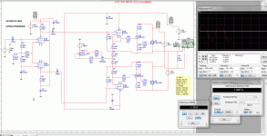
From the schematic, I cannot see why you have such an abrupt phase shift around 500Hz, but you could probe a frequency sweep with the CRO at various points along the circuit since there is no (global) feedback. That should reveal it.
Hugh
Thanks, it was a quick idea to let see that it can work, I have to put fasesplitter and such, but as example that quasy can work like this yamaha idea, the modern jfets has no -40 volt Vgso but -5 volts, so everything get different.
I will also try a allfet version, with al are jfets, cascode with these devices give liniarity.
good stuff to try, over a couple days I receive 6J9P and 6J49P penthodes for testing.
these schematic I use now see post 99, and sound here, some harsh because of youtube compression I can nowhere post pure wav.
6C4N-EB hybride - YouTube
it is much fun testing, the faseflip is only when simulate, not in real multisim has bad models in them, I need to find better ones.
have a good day.\ evening.
What do you mean ditch the ss devices, you mean the dn 2540 devices? the drive I need for the semisouth is to big for tubes, therefore I use
them, now as test I search for others also, I have removed the CCS and voltage of 200 volt because it is not needed with modern jfets, the old 2sk77 has Vsgo of -40 volts these
days it is +1 to -5.
Therefore the B1 can not be used anymore, al there fets are so special.
them, now as test I search for others also, I have removed the CCS and voltage of 200 volt because it is not needed with modern jfets, the old 2sk77 has Vsgo of -40 volts these
days it is +1 to -5.
Therefore the B1 can not be used anymore, al there fets are so special.
some change in the schematic, the amp has in in it a source follower and a drain follower in one power stage, that is quasi, therefore I have need of a fasesplitter who is also drive it with one output much lower then the other, I hope you understand me, the cortina fasesplitter has also to be one what do not amplify otherwise it hase to much and then I need feedback.
a long tail fasesplitter is the one I need I think.
First I need a model of the new power jfets, and some in real to test it like this, there a a lot more possibillities, I am a little curieus about them this moment
one picture without feedback the other one with, with feedback the distortion was higher, but it is simulation, it is not perfect.
regards
Attachments
Last edited:
ahaaa the Constellation Audio uses two balanced single ends, do we not call this circlotron for a part, difference only, voltage on speaker cable to ground. and afcourse
both sides have the same way of amplifying, quasy do have not, there is one part a amp, the other a follower..
I think a circlotron is very balanced with only one kind of mosfet or transistors, expecially higher frequenties in audio is prone to imbalance, making sound very harsh.
regards
both sides have the same way of amplifying, quasy do have not, there is one part a amp, the other a follower..
I think a circlotron is very balanced with only one kind of mosfet or transistors, expecially higher frequenties in audio is prone to imbalance, making sound very harsh.
regards

Last edited:
Hi all
I have found a model here of a semisouth J-Fet, I have simulate a quick drawn amp topology to test it.
for as far the mosfet go, it is faster, but has more distortion as used in ab biassed amp, in class a it get less then a normal mosfet.
I have not the idea that if I made a quasy only Nfet amp that using semisouth is better, I need a beefy driver that is for shure.
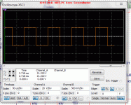
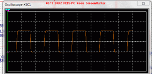
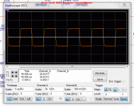
I have some pics with sqare waves to see what is differend.
The prise fopr them is high, it is not better if used without class A idle currents, it need big current to go liniair, so in the nelson pass amps it go better then normal mosfets, I have to say, it is simulation, I have not listen yet, I will do if $ are down.
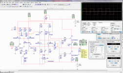
squares are picture 1 =10Khz SJEP120R100A picture 2 =100Khz SJEP120R100A picture 3 =100Khz 2SK1058, jou see slight slewing with 2sk1058 that is the only differency, last picture the schematic for testing.
regards and nice weekend.


Last edited:
- Status
- Not open for further replies.

