Attachments
Nopes, unless j Carr worked for Luxman back in 1982, the luxman predates all these by by at least 20 years with the exact same voltage amplification scheme. ")
The funniest part is that so called western audiophiles used to and still do call japanese designs junk but are now copying their designs from near 30 year old amps and calling it high end. 
The funniest part is that so called western audiophiles used to and still do call japanese designs junk but are now copying their designs from near 30 year old amps and calling it high end.
Bernhard said:C4 is still in the signal path.
Yes, that's not a problem for me.
homemodder said:Nopes, unless j Carr worked for Luxman back in 1982, the luxman predates all these by by at least 20 years with the exact same voltage amplification scheme.
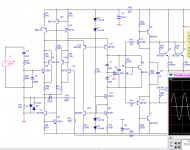
Do you have this schematic homemodder? It'd be nice to see the original.
All my tinkering last night went out the window. Multisim locked up and shut down and I lost all of the progress I made (autosave is NOT turned on). I'll see if I have some time this evening to play some more.
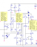
I ve lost half of my schematics, due to a harddrive failure but if I remember correctly the model is L500 or L450. Its the exact same circuit except Roender has a constant current source for the cascode whereas the luxman used a resitor to bias the cascode dynamically. Luxman also used a EF buffer before the outputstage but this was needed as it used a servo for dc offset instead of a cap at the feedback node.
Oh theres one more difference instead of leds, Luxman used diodes, the rest is exactly the same. The Luxman used a class A outputstage with it though. The design date was 1981 or 1982 , I remember this much because when I was looking at the schematic I was thinking heck I was only 10 years old back then.
I might still have a small hand drawn schematic of that inputstage because I wanted to try build a preamp out of it years ago but couldnt find the fets. I ll search the net again for luxman schematics, they have some excellent designs, years ahead of their time, I will most probably find this one.
homemodder said:its the L550,
Thanks homemodder,
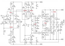
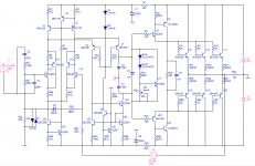
I found it but it the whole amp schematic. Some ideas for me here.
I cut this part out:
Attachments
Jacco, that amp looks good, what is it about the 550 II series, what changes were made ?? I like these Luxman amps, they are very well designed, never listened to one but there are many people critisizing them and I find this unbelieveable. I have just finished prototyping and modifying a design based on a elite series Pioneer from 1988, another hell of a good amp, with just 24 transistors I easily get full power THD20 figures of quite a bit less than 0.001 200w and here we are 20 years later coming up with incredible complex designs to achieve the same. To me it sounds excellent, every bit as good as electrocompaniet. I dont understand the reason these japanese amps are said to sound bad, only if its a parts thing and then we are not talking of the transistors used. Ive come to highly respect some of these japanese designs.
MJL21193, yep thats the one. Ill make a clone of it on ltspice and see what it can do.
MJL21193, yep thats the one. Ill make a clone of it on ltspice and see what it can do.
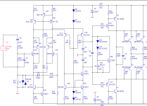
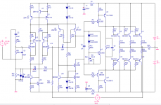
John,
maybe we can clear this up. Firstly, R2 is a current source (should have high impedance, positioned on the collector side), providing current for D1 and D6, which form a voltage reference (should have low impedance, positioned on the emitter side). An active current source has much higher dynamic impedance than a resistor.
D2 and D3 are not needed.
- Status
- This old topic is closed. If you want to reopen this topic, contact a moderator using the "Report Post" button.
- Home
- Amplifiers
- Solid State
- Abomination! or Painting a Mustache on the Mona Lisa meets the Island of Dr. Moreau