I'm open to suggestions...") One thing is that it needs to stay bjt - no FETs.
One thing is that it needs to stay bjt - no FETs.
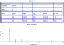
I'm liking the way this one looks in simulation. It has stronger H2 than H3 and not much above -125db for higher order stuff.
It has very good PSRR.
I would like to try the thermal trak NJLs as drivers, with their diodes looped into the Vbe multiplier. Something different.
One thing is that it needs to stay bjt - no FETs.I'm liking the way this one looks in simulation. It has stronger H2 than H3 and not much above -125db for higher order stuff.
It has very good PSRR.
I would like to try the thermal trak NJLs as drivers, with their diodes looped into the Vbe multiplier. Something different.
The high rail voltage is my way of avoiding clipping. The gain will be set so that at max output (per input sensitivity) the amp never reaches the full rail potential. Clipping headroom.
Besides, I have a 50-0-50 I need to use.
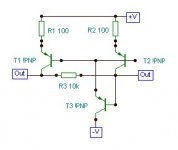
I'm a little confused about what you are referring to. U2 is bias for the VAS CCS (U1 & U3).
I have shifted things around to make things more clear:
Besides, I have a 50-0-50 I need to use.
I'm a little confused about what you are referring to. U2 is bias for the VAS CCS (U1 & U3).
I have shifted things around to make things more clear:
Attachments
Best so far !!
Hi , john. I need some "havoc" in my life.
I simulated it. Very , very good.
The only changes I made was a triple for the OPS , just
a led for U2 (your active source on negative rail does all the work)
H5/7 were -140db .. wow ! and Psrr was -100db.
I was going to do the VSOP (another folded design) but yours
beat it. (I also have seen it in completed form )
OS
Hi , john. I need some "havoc" in my life.
I simulated it. Very , very good.
The only changes I made was a triple for the OPS , just
a led for U2 (your active source on negative rail does all the work)
H5/7 were -140db .. wow !
and Psrr was -100db.I was going to do the VSOP (another folded design) but yours
beat it. (I also have seen it in completed form
)OS
Attachments
Hi,
is R33 needed? The diodes pass the fault current and the NFB ties the inputs to the output.
What happens if you reduce R4 & R39, to increase the pre-driver current to somewhere between 5mA and 7mA? 82r to 130r?
Are the integrated diodes monitoring the correct junction temperatures?
For the CFP shown the bias voltage is across the pre-driver and output device base emitter junctions. Surely the temp comp should be applied to either the pre-driver and/or to the output devices.
The 1943/5200 will not like the +-70Vdc supplies. They will run hot due to ~200mA of output bias current (Pq=28W) and have a very low SOAR @ this combination of voltage and temperature.
Yes, I like the idea of using the high quiescent voltage to give clip free music dynamics, but I don't like the resulting schematic you've posted to achieve those dynamics. I see the solution as either a much lower supply voltage or a much more robust output device.
Re: Best so far !!
Thanks OS,
One LED or 2 diodes for U2 give the same result. Thank Lumba for the CCS.
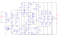
It's still a work in progress.
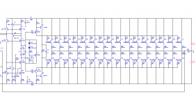
One thing I want to do is work with a different layout for this one. Something like this:
ostripper said:Very , very good.
The only changes I made was a triple for the OPS , just
a led for U2
Thanks OS,
One LED or 2 diodes for U2 give the same result. Thank Lumba for the CCS.
It's still a work in progress.
One thing I want to do is work with a different layout for this one. Something like this:
Attachments
AndrewT said:Hi,
is R33 needed? The diodes pass the fault current and the NFB ties the inputs to the output.
Hi Andrew,
First off, as I mentioned above, this is still a work in progress. Everything is subject to change. I'm in no rush.
R33 (on the latest posted schematic) isolates common ground from signal ground.
AndrewT said:
What happens if you reduce R4 & R39, to increase the pre-driver current to somewhere between 5mA and 7mA? 82r to 130r?
According to the simulator higher order harmonics increase. Whether this is accurate or not I can't say. What I can say is that the amp works fine with this current through as shown on the Abomination.
AndrewT said:
Are the integrated diodes monitoring the correct junction temperatures?
For the CFP shown the bias voltage is across the pre-driver and output device base emitter junctions. Surely the temp comp should be applied to either the pre-driver and/or to the output devices.
The master and slave of the CFP drivers, along with the Vbe multiplier and the entire output stage will be on the main heatsink. I see no problems.
AndrewT said:
The 1943/5200 will not like the +-70Vdc supplies. They will run hot due to ~200mA of output bias current (Pq=28W) and have a very low SOAR @ this combination of voltage and temperature.
Yes, I like the idea of using the high quiescent voltage to give clip free music dynamics, but I don't like the resulting schematic you've posted to achieve those dynamics. I see the solution as either a much lower supply voltage or a much more robust output device.
Like I said - a work in progress. The choice of outputs is not firm yet, but I don't see a problem with the 5200/1943 here. They are 230V devices.
I'm not sure where you got the 200mA idle current figure from - the correct idle current for this amp should be 80-90mA per device.
like you said "a work in progress".
Does 200mA come to around 67mA/device?
The 1943 are down to 1A @ 70Vce.
De-rate for Tc=55degC and that 1A falls to 760mA.
The design uses up ~85mA just for quiescent bias.
That does not leave much for driving 16ohm speakers.
8ohm is going to be a severe load for 1943/5200.
When cold the 1943/5200 are 150W and 230Vce0 devices that are now 53W and 70Vce devices in this design.
Relax Andrew. I understand the SOA of the 5200/1943 are pushed in this instance, just as they are (even more so) in my Patchwork amp. Given that I use more than adequate heatsinks and that I'm not playing a nightclub, I think some concessions can be made. Sure, there's a more robust choice. Is it absolutely necessary for this application? Not likely.
In the end, when it comes time to actually build this amp, I'll re-examine the choices. I don't have enough of any output device (except thermal traks) to build a pair of these.
In the end, when it comes time to actually build this amp, I'll re-examine the choices. I don't have enough of any output device (except thermal traks) to build a pair of these.
MJL - One thing I want to do is work with a different layout for this one. Something like this:
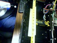
I like that style , too .. but with my HS (attached) ,I would only be able to "hit" 2 of my heatsinks with a 9" board.I want to at least
get 3 for the big amps (there are 4 total per side) and 1 for the
lm3886's.
The only option I seem to have is the 1.5" "L" x 18". I did put
U2 back in as with the led ,.1v offset was observed (you got it
right the first time, U2/1/3 act as a balanced current source/cm).
Do you have abominations still playing around your house ?
How do they sound ?
OS
Attachments
ostripper said:
I like that style , too .. but with my HS (attached) ,I would only be able to "hit" 2 of my heatsinks with a 9" board.I want to at least
get 3 for the big amps (there are 4 total per side) and 1 for the
lm3886's.
Do you have abominations still playing around your house ?
How do they sound ?
OS
I have one complete Abomination that I listened to shortly after it was built. My problem here is that my main speakers are active, so I had to use an older one that has a substitute tweeter - not the one the crossover was designed for. Sound quality is very high in my estimation.
The layout would be best used directly on a large heatsink. I have some ideas for either making it extremely narrow or excessively wide. I need to finalize the circuit first though...
AndrewT said:
2pair of mj21193/4 will roughly match 8pair of 2sa1943/c5200 @ 70Vce and Tc=55degC.
It just seems to me that choosing that existing 50Vac transformer and your existing output devices is not a great combination.
I understand. I'm a big fan of the MJL21193/94's (and the TO-3 version) and I may go this way.
It's not a matter of using the transformer - it's how I see this amp. Zero clipping potential, that's what the high voltage gives. If I didn't have a 50-0-50, I'd be looking for one.
BTW, I have a new AndrewT version brewed up. SOA aplenty!!
Attachments
That's funny..BTW, I have a new AndrewT version brewed up. SOA a plenty!!
One thing.. have you checked the OLG ofthis thing ? It is 90Db + with unity at 8mhz !! (too much).
that is with U2 which acts like a typical self CM doubling or tripling
the loop gain !
What is blowing my mind is that it still IS working at this level
with little ringing or oscillation.
OS
Attachments
ostripper said:
That's funny..
16 pair!

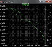
I'm not sure how you got the OLG plot, mine (done last night) looks like this:
Attachments
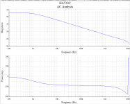
I'm not sure how you got the OLG plot, mine (done last night) looks like this:
I'm not sure , either. I am using fairchild KSC1845 models for inputs (too much gain?)
My slope is the same as yours (89 degree phase/flat to UG)
but the UG is 8mhz and total gain is 88db with your 91r degen.
OS
ostripper said:
that is with U2 which acts like a typical self CM doubling or tripling
the loop gain !
U2 is bias for U1 and U3. These are the current source for the VAS.
U25, U26 (near the bottom) are the current mirror.
ostripper said:
I'm not sure , either. I am using fairchild KSC1845 models for inputs (too much gain?)
My slope is the same as yours (89 degree phase/flat to UG)
but the UG is 8mhz and total gain is 88db with your 91r degen.
OS
My pick for small signal are the 2SC2631 and the 2SA1123 both of these the "R" version with Hfe 130-220.
I don't have models for these but used the 2SA970/2240 as a good substitute. Both of these have medium gain.
 , I'm happy now. 1mhz UG /53db total (more like the original).
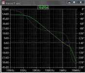
- Status
- This old topic is closed. If you want to reopen this topic, contact a moderator using the "Report Post" button.
- Home
- Amplifiers
- Solid State
- Abomination! or Painting a Mustache on the Mona Lisa meets the Island of Dr. Moreau