Hi Tim
The link is interesting, Ive see some power amps designs based around that topology and would have thought it performed better than the results obtained by Ciuffoli. Not bad though, I guess one could always beef up that output stage.
Tim you maybe right about there being something else too, but in tube circles guys are well aware that the 2nd harmonic is vital to the warm tube sound. They are not like SS guys they do a lot of research in listening tests, I have a test done by some guys whereby they change the spectra of a tube amp by manipulating if I can remeber correctly the feedback. They came to the conclusion the less 2nd harmonic the less warmth, but all 2nd harmonic is bad as it makes the amp muffled. Its a very interesting test they did, to see what effect the spectra have on amps. I could find it with some time, its somewhere on my harddrive, if you interested in reading it.
I was looking a bit into the Superlinear-circuit yesterday in the evening, but to my surprise I cannot get the expected gain out of it.
The Pioneer schematic says that the gain is set by the ratio RL/RE which is 10:1 in Andrea's headamp. A quick simulation of the superlinear circuit with these values brings a gain of less than 1.
Does anybody also experiences that?
To my understanding the circuit should work as described and also the gain should be about that what the ratio says (I'm wondering about the influence of the current mirror loading of the common-emmitter stage though; should also give gain) - so is it again a Spice-fault? Or just a mistake on my side?
Have fun, Hannes
TimS,
Both FFT and wavelet analysis have serious laxities.The fundamental problem is, (see Heisenberg) that the conjugate variables, position and momentum of a moving particle cannot be determined simultaneously. The more precisely one is known, the less precise becomes the other. (Listening is the only way to know).
That's a hazy term. What do you mean by it?I believe they hear the shape of a sound.
Both FFT and wavelet analysis have serious laxities.The fundamental problem is, (see Heisenberg) that the conjugate variables, position and momentum of a moving particle cannot be determined simultaneously. The more precisely one is known, the less precise becomes the other. (Listening is the only way to know).
Lumba Ogir said:
Both FFT and wavelet analysis have serious laxities.The fundamental problem is, (see Heisenberg) that the conjugate variables, position and momentum of a moving particle cannot be determined simultaneously. The more precisely one is known, the less precise becomes the other. (Listening is the only way to know).
Lumba,
Are you claiming that quantum effects, like the Heisenberg incertitude principle, have an audible impact?
Well, well.
If one says Heisenberg uncertainty, I say classical limit.
Have fun, Hannes
PS: state whatever one wants to state - everybody is free to do that, but don't put on personal opinions a cloak of pseudo physics. Other people just don't understand and could take it as a fact.")
EDIT: @Ovidiu: any comment on Pioneer's superlinear-circuit? I thought of using that as VAS in a small amp, but sim produces banana (as my collegue says).
If one says Heisenberg uncertainty, I say classical limit.
Have fun, Hannes
PS: state whatever one wants to state - everybody is free to do that, but don't put on personal opinions a cloak of pseudo physics. Other people just don't understand and could take it as a fact.
EDIT: @Ovidiu: any comment on Pioneer's superlinear-circuit? I thought of using that as VAS in a small amp, but sim produces banana (as my collegue says).
homemodder said:not like SS guys they do a lot of research in listening tests
Do some more research and you'll find commercial SS amps with variable feedback.
h_a said:any comment on Pioneer's superlinear-circuit? I thought of using that as VAS in a small amp, but sim produces banana
Schematic?
Hannes,
frankly, I did not count on getting support from you, it has never happend before (but that does not make me like you less).
Could someone kindly increase the depth of my comprehension, why that circuit would be super linear, current mirrors have a negligible ability to work miracles.
frankly, I did not count on getting support from you, it has never happend before (but that does not make me like you less).
Could someone kindly increase the depth of my comprehension, why that circuit would be super linear, current mirrors have a negligible ability to work miracles.
if it is the same circuit i'm thinking of, it's just a "marketing-ploy" type of name by pioneer.
pretty old - early to mid 80's ?
mlloyd1
pretty old - early to mid 80's ?
mlloyd1
Lumba Ogir said:...
Could someone kindly increase the depth of my comprehension, why that circuit would be super linear, current mirrors have a negligible ability to work miracles.
Lumba Ogir said:TimS,
That's a hazy term. What do you mean by it?
I was meaning when you hear a drum beat you hear the time domain impulse (or what I called shape), you don't hear the flat spectral response.
Cheers
Tim
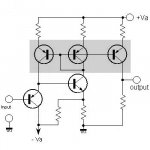
@Ovidiu: your wish is my command, find the schematic attached. It's as mlloyd1 says a Pioneer circuit from the 80ies (used in their big buck amps); however what they claim is impressive: a tenfold reduction in THD and I find it especially interesting that it's claimed to work best for large voltage swings (see THD vs. output plot at
http://www.audiodesignguide.com/Headphone_amp/headphoneamp.html
a bit down on that site).
The marketing says it works by reinjecting the distorted current of the npn back into the input pnp by the current mirror (however out of phase), thus cancelling distortion.
If that works it would be a nice VAS for a low power amp, as it should have plenty of gain due to actively loading the npn (plus the claimed RL/RE ratio).
@Lumba, thanks for your kind words. I respect your view points, and while I usually not comment, you now and then touch a sensitive spot
Have fun, Hannes
Attachments
syn08,
Hannes,
TimS,
Just use your ears.
mlloyd1,
No, I`m saying that those analyses depict sound poorly.Are you claiming that quantum effects, like the Heisenberg incertitude principle, have an audible impact?
Hannes,
Obviously, you don't understand. Spectral components are not traceable at any given time instant.don't put on personal opinions a cloak of pseudo physics. Other people just don't understand and could take it as a fact.
TimS,
No, the ear`s phenomenal sensory system in conjunction with the brain`s even more fenomenal compiling and analyzing ability effectuate a spectral resolution containing far more wealth of sensitiveness and detail than any clumsy tool can ever accomplish.I was meaning when you hear a drum beat you hear the time domain impulse (or what I called shape), you don't hear the flat spectral response.
Just use your ears.
mlloyd1,
Right, it`s exactly what it is, a marketing-ploy.if it is the same circuit i'm thinking of, it's just a "marketing-ploy" type of name by pioneer. pretty old - early to mid 80's ?
Hi All
I found that using a mosfet in the output stage I can get lower distortion at lower bias currents into 32R. The downside is it can only swing to within 5 volts of the rail voltage, but that is still a good +/- 10V with a 15V rail.
Cheers
Tim
p.s.
The parts have finally arrived, it turns out that the versions of ST D44H11 and D45H11 were not RoHS compliant and were not being stocked any more so i changed my order to be the ON semi D44H11G and D45H11G.
I will let you know how the prototypes work out.
Using BJT+MOSFET output is a good option.
As the Gates are voltage driven, the load for the BJT is pretty nice/light.
You use 6-7 mA to drive the MOS. A good choice.
Especially if you use IRF610/9610 or IRF510/9510, which would be better than the higher rated IRF540/9540.
The bias of the MOSFET can make a big difference.
They tend to make less higher order harmonics at more current.
For example as high as 150-250mA will leave some 2nd order while suppress other.
This is the reason I see all these Headphone amplifiers/buffers, running much more Class A MOSFET current than is actually needed to drive 32 Ohm phones.
Hi Tim,
I have built several diamond buffers and have been pretty happy about the performance. Mine generally differ from yours in that I do not use mosfets for output, rather an EF pair and an extra diode in series with the input emitters (Q3, Q4). My current sources are made from a red LED and transistor. They are more stable with temperature changes.
I find that mosfets are anything but linear unless you run them at very high currents (compared to what I might). They need negative feedback and they are still less linear than a BJT.
If you mount Q3, 4, 19 and 20 on a common heat sink, the bias current will be more stable. Not considering your mosfets that require bias correction themselves.
My simple one drove speakers nicely (at low levels), I was shocked at how good it sounded. Those were 8 ohm, so higher resistance headphones should be possible.
-Chris
Hi Chris
I too did start with bipolar output devices and then later found the the mosfet gave me lower distortion driving a 32R load. But if it came to driving a 1k load the Bipolar had the edge.
And in the end I was going to use the bipolar version, because it was going to be the basis of a preamp as well as drive headphones I decided I would rather have the lower distortion into 1k and live with the higher distortion into 32R.
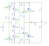
But since then, somebody gave me a very good suggestion on another, similar, amp and when implemented in this circuit it improves the distortion significantly (ie close to be unmeasurable in my simulation) into 32R. (I attached the circuit)
Your idea to temperature couple the input transistors is a good one and now I am thinking of saving myself the troubles and using the THAT340 quad transistor pack.
I will also be trying the LED transistor constant current, it would be nicer to have a simpler circuit.
Cheers
Tim
I too did start with bipolar output devices and then later found the the mosfet gave me lower distortion driving a 32R load. But if it came to driving a 1k load the Bipolar had the edge.
And in the end I was going to use the bipolar version, because it was going to be the basis of a preamp as well as drive headphones I decided I would rather have the lower distortion into 1k and live with the higher distortion into 32R.
But since then, somebody gave me a very good suggestion on another, similar, amp and when implemented in this circuit it improves the distortion significantly (ie close to be unmeasurable in my simulation) into 32R. (I attached the circuit)
Your idea to temperature couple the input transistors is a good one and now I am thinking of saving myself the troubles and using the THAT340 quad transistor pack.
I will also be trying the LED transistor constant current, it would be nicer to have a simpler circuit.
Cheers
Tim
anatech said:Hi Tim,
I have built several diamond buffers and have been pretty happy about the performance. Mine generally differ from yours in that I do not use mosfets for output, rather an EF pair and an extra diode in series with the input emitters (Q3, Q4). My current sources are made from a red LED and transistor. They are more stable with temperature changes.
I find that mosfets are anything but linear unless you run them at very high currents (compared to what I might). They need negative feedback and they are still less linear than a BJT.
If you mount Q3, 4, 19 and 20 on a common heat sink, the bias current will be more stable. Not considering your mosfets that require bias correction themselves.
My simple one drove speakers nicely (at low levels), I was shocked at how good it sounded. Those were 8 ohm, so higher resistance headphones should be possible.
-Chris
Attachments
I am sorry to contradict you Lumba, but the distortion would increase considerably if i implemented your suggestions.
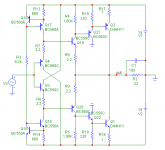
The reason behind Q21 and Q22 is to isolate Q19 and Q20 from the additional current drawn from the bases of Q1 and Q2 while they are driving a significant load. The additional current causes a current mismatch between Q4,Q19 and Q3, Q20 and so affect the distortion cancelling which is the big advantage of using a diamond front end.
Moving R17 and R16 to the collector side will just cause a loss of voltage swing, because the high collector impedance, but not much else.
I suspect you are thinking that I should implement a compound emitter follower , and the output circuit is similar, but as I said I need Q21 and Q22. Though it does make me think of a variation I haven't tried yet
- Home
- Amplifiers
- Solid State
- Improved Diamond Buffer Design