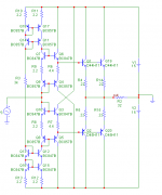
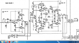
Guys can we talk about this circuit some more? Its excellent sound has even prompted me to build a to92 version of it and the thermal drfit is unmanageable. Even if i trim one of the current mirror resistors to the lowest offset it will drift to 100mv range depending on the airflow.
Im thinking monolithics and a single heatsink over all of them is the only way to go. Or is there another method? (Besides servos) ((and also i really wanna keep using this circuit over others because i believe there is some magic to cascoded mirror sound.))
Im thinking monolithics and a single heatsink over all of them is the only way to go. Or is there another method? (Besides servos) ((and also i really wanna keep using this circuit over others because i believe there is some magic to cascoded mirror sound.))
Attachments
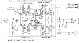
I mean either thermally couple Q4 with Q1 or Q19 or both.
And couple Q3 with Q2 or Q20 or both.
Idea case is that all transistors are on the same radiator.
But you can also split this like described above.
The mirrors are a different story and might contribute to drift as well.
Transistor pairs that should be thermally coupled:
Q17+Q18
Q15+Q16
Q6+Q7
Q5+Q8
The cascode transistors should not matter in terms of drift.
I'm not a specialist for Diamonds either, still struggling to get mine working properly.
Im not a designer, just a builder. From building several diamond circuits tho i have noticed that ones with current mirrors always have more aggresive drift. Tim's is the worst in that regard. I can make the dc offset jump to 100mv+ just by blowing on the board. The tradeoff is that it sounds better than most other buffers i have probably due to the high psrr besides the low distortion.
Youre right tho. I think the best solution is to smd everything then stick a heatsink on top.
Youre right tho. I think the best solution is to smd everything then stick a heatsink on top.
Im not a designer, just a builder. From building several diamond circuits tho i have noticed that ones with current mirrors always have more aggresive drift. Tim's is the worst in that regard. I can make the dc offset jump to 100mv+ just by blowing on the board. The tradeoff is that it sounds better than most other buffers i have probably due to the high psrr besides the low distortion.
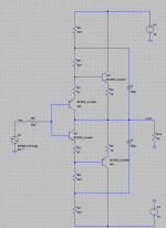
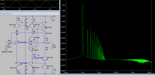
You can make solution in between. Bootstrap resistor emitter of input transistor. Use 2 resistors in series than connect capacitor in the middle of resistor to output.
You can make solution in between. Bootstrap resistor emitter of input transistor. Use 2 resistors in series than connect capacitor in the middle of resistor to output.
Hi im about to try this this weekend. In what values do you recommend the resistors be split?
Its my understandking that the bias point wont change as long as the resistors in series are same value as the original? And the value of the inside resistor along with the cap will determine the lpf value?
Hi im about to try this this weekend. In what values do you recommend the resistors be split?
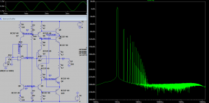
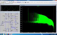
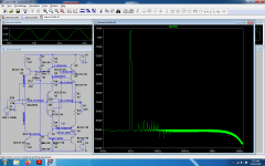
I make fast simulation. Without bootstrap THD at 20kHz 2Vpeak = 0.000449% and with bootstrap = 0.000163%. It reduce a bit. You can play the simulation until you find your goal. It is simple.
Attachments
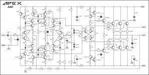
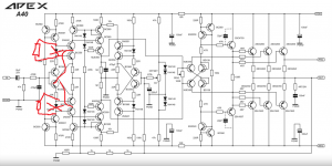
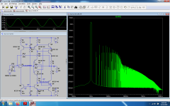
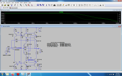
For Diamond Buffer IPS here is one example...APEX A40...this is improved Diamond Buffer for IPS and also for temperature tracking with TEF as OPS.
This is working amplifier...and i im posting here schematic as example as another solution how can be made with IPS and VAS....so put this schematic into MicroCap and play with values until you got excellent results.
This is working amplifier...and i im posting here schematic as example as another solution how can be made with IPS and VAS....so put this schematic into MicroCap and play with values until you got excellent results.
Attachments
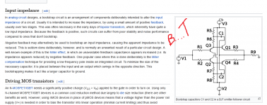
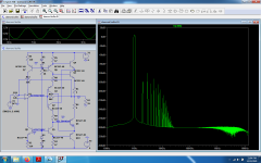
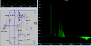
It actually destroys the whole harmonic profile.Unfortunately the wikipedia article promotes this complete nosensical schematic where c1 and c2 are not just completely useless but actually harmful ...Wow thats substantial. What does it do to the harmonic profile?
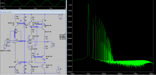
Next b...t is the apex 40 schematic whose diamond buffer is wrongly biased and it doesn't give enough breathing room to any of the transistors in the input buffer.It relies heavily on feedback to get rid of the bad things done with the basic design.Just sim it with my simple mods, compare it with any of the other schematic and you'll see the difference easily.Wire it as in my sim and you'll see much better results than in the capacitor bootstrapped and combined cap + rail bootstrapped version from post 23. The way i wired the transistors was only to take care of the thermal regime of the transistor, the actual resistor values are completely different as i did it for germanium transistors so two resistors are actually lower value NTC's...
Attachments
Last edited:
coupled mirrors in general , like in IC's need tempco biasing and in integrated vresion is much easier to be done, but you might wanna consider studying these circuits:Guys can we talk about this circuit some more? Its excellent sound has even prompted me to build a to92 version of it and the thermal drfit is unmanageable. Even if i trim one of the current mirror resistors to the lowest offset it will drift to 100mv range depending on the airflow.
Im thinking monolithics and a single heatsink over all of them is the only way to go. Or is there another method? (Besides servos) ((and also i really wanna keep using this circuit over others because i believe there is some magic to cascoded mirror sound.))
Attachments
might be interested in this:For Diamond Buffer IPS here is one example...APEX A40...this is improved Diamond Buffer for IPS and also for temperature tracking with TEF as OPS.
This is working amplifier...and i im posting here schematic as example as another solution how can be made with IPS and VAS....so put this schematic into MicroCap and play with values until you got excellent results.
Attachments
Thanks dreamth. Some food for thought. However at the moment im rather deadset on getting TimS' original circuit thermally stable. I had another listen last weekend and its really the best thing that ive come across. Sounds like a good passive, meaning no distortion besides little bit of second harmonic but with the dynamic of a proper buffer. It trumps other handful of designs ive tried including b1, hawksford, jlh buffer ect.It actually destroys the whole harmonic profile.Unfortunately the wikipedia article promotes this complete nosensical schematic where c1 and c2 are not just completely useless but actually harmful ...
Next b...t is the apex 40 schematic whose diamond buffer is wrongly biased and it doesn't give enough breathing room to any of the transistors in the input buffer.It relies heavily on feedback to get rid of the bad things done with the basic design.Just sim it with my simple mods, compare it with any of the other schematic and you'll see the difference easily.Wire it as in my sim and you'll see much better results than in the capacitor bootstrapped and combined cap + rail bootstrapped version from post 23. The way i wired the transistors was only to take care of the thermal regime of the transistor, the actual resistor values are completely different as i did it for germanium transistors so two resistors are actually lower value NTC's...
So onto making this one thermally coupled. My ideas are
1. Smt everything then ceramic heatsink the target components.
2. Use to-126 transistors for input and output (bd139?) with a layout such that i can bind the each quad pairs together with an M3 bolt
3. Use quad bjts instead such as MMPQ2222A and its complimentary (the cheapest of its kind i could find)
Im thinking that method 1 will be least effective yet circuitwise the least noise (i can pick quality transistors) and 2 will couple really well but i dont know how medium power bjts are ever good for input devices, and 3, it just seems pricy if im gonna go with a THAT array for noice concerns.
Maybe theres more viability to method 2 and 3 that my limited knowledge cant foretell right now? I appreciate your thoughts
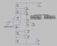
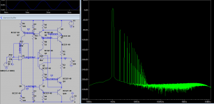
Unfortunately i don't have the right germanium trz models, but this is what i'm going to play around this christmas with q1, q4 germanium, r1...r2=2...22 ohm and r8, r9 =NTCThanks dreamth. Some food for thought. However at the moment im rather deadset on getting TimS' original circuit thermally stable. I had another listen last weekend and its really the best thing that ive come across. Sounds like a good passive, meaning no distortion besides little bit of second harmonic but with the dynamic of a proper buffer. It trumps other handful of designs ive tried including b1, hawksford, jlh buffer ect.
Attachments
Wow most impressive. Reminds me of this circuit https://www.diyaudio.com/community/threads/latfet-amp-based-on-philips-ah578.367494/ but even more integrated. I was actually looking for a design like that a while back- nested opamp but with a boostrap.
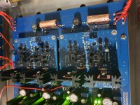
Please let me know if you need a beta tester. The modular preamp i showed earlier makes trying out different circuits extremely economical.
Please let me know if you need a beta tester. The modular preamp i showed earlier makes trying out different circuits extremely economical.
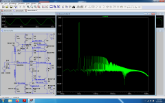
I'm thinking of using germanium trz for all q1...q4 so that i have better clipping behaviour although with a fast enough rail to rail low current op-amp i might dump d3, d4 and rely on feedback .Not sure what exactly that opamp might be though as ada4896 killed my computer speed in transient mode in both inverting and decoupled non inverting mode showing me some 500mv output offset in any situation...thus assimetrical clipping...I'm open for suggestions.
Even for germanium i can have pretty decent clipping behavior, but for germanium is usually better with lower supply so i could have it on batteries.
Even for germanium i can have pretty decent clipping behavior, but for germanium is usually better with lower supply so i could have it on batteries.
Attachments
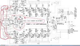
Finally got some positive results closer to clipping, but it doesn't feel well with only one diode bias per rail...I was looking at ada4896 model cause i have some ada4898 and 4899, but the latter ones aren't rail to rail op-amps...I'm sure germanium transistors will help a bit on the clipping side, yet q5...q10 will stay silicon for better PSRR , lower leakage of the whole circuit and speed...With only one diode i get very weird results...but no simulator is better than its user ")
Attachments
- Home
- Amplifiers
- Solid State
- Improved Diamond Buffer Design