Primarily the use of cascode (CB) current buffers upon common-emitter (CE) transconductance stages increases bandwidth and stabilizes gain by holding collector voltage constant for the CE stage. This is readily available knowledge.
The main question is: In case of low-gain CE stages with substantial signal voltage arising on relatively large emitter ballast resistors (approximately negatively proportional to base signal), does it ever make sense to buffer the base (of CE stage) signal with an emitter follower to drive cascode "ground" reference voltage, so that the CE stage sees constant C-E voltage at the expense of applying signal to the CB stage?
Would this decrease the advantages of the CB stage by re-introducing the Miller effect (remember that CB base drive has been buffered by an emitter however), or are the potential improvements of stabilizing CE stage C-E voltage worth the compromise (including additional semiconductor components) if high dynamic voltage range (significantly varied CE emitter voltage) is desirable?
Any thoughts on this would be greatly appreciated!
Happy listening!!
I do not often use cascode.
The few times I use it, is 9 times out of 10 in the VAS.
It is very much dependent on the actual transistors, voltage and currents used,
if there is a real benefit of using cascoding.
At least to justify the increased complexity and deal with drawbacks.
Not all parameters gets better with cascode.
There are parameters that will be less good.
Bottomline:
There are no precise rules for when and how to cascode.
Depends on the circuit, the source signal, the output signal and used transistors.
And even in those cases when a cascode can improve,
there are many times other ways to deal in a more simple way.
In my opinion.
Regards
acoustixman said:
Would this decrease the advantages of the CB stage by re-introducing the Miller effect
In my opinion: YES, exactly.
Alternatively you can use something like Hawksford's 'cascomp' or reference the CB stage to the emitter of CE stage (even with a higher voltage JFET if you like).
Kind Regards,
Adam
accompanying schematic
Thanks all for the replies;
lineup: I didn't intend to be debating the use of the cascode topology itself. Agreed; like all practical circuit implementations it has real-life limitations and represents a form of compromise (rail voltage loss margin being the greatest in my opinion). These limitations do not generally include bandwidth or linearity in my experience. As such I use them for virtually all Miller-sensitive stages in my own audio work. Such high GPB & Hfe transistors are now available (non-darlingtons in the 1,000's) [generally at "low" C-E voltage ratings] that interstage loading can be minimized and this is a substantial benefit alone, but they need to be protected under a cascode stage in the VA section in particular to defend their ratings.
darkfenriz: I feel that you understood my question entirely, but I'm wondering if the effects would quantitatively outweigh those of having variance in the C-E voltage of the gain transistor.
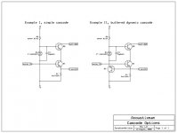
Lumba Ogir: I never talk loosely. Our terminology is probably different (I'm a chemical engineer, not electrical unfortunately so I just have to pick this stuff up as I go)... I have included a diagram for clarity:
In the diagram, I have omitted frequency and temperature compensation elements and other distracting supplemental componentry, other than the zener bypass caps, to help imply that the voltage DROP there is to be maintained constant, even if it changes relative to the rails in "option II".
It is to be assumed that the ballast resistor is significant enough to provide substantial AC signal at "V emittr", such that with "Option I", the C-E voltage on Q1 will surely decrease as "error IN" increases. This would happen likewise in "Option II", but this voltage is applied via buffer to the Zener, so that while the cascode voltage "slides up" in response, the C-E voltage would be held approximately constant. In this state, Q1 will be "optimally cascoded", but only because of the base of Q2 being driven with signal. This is where the main question comes in:
Does the base of Q2 being driven with signal negate the effects of the cascode in terms of the final collector being able to impose its Miller capacitance on the base, or if the voltage "interval generator" impedance is low enough, will that dissapear? Miller himself proposed that the degree of effect would depend on source impedance. I'm making no statement about the Zener bias impedance, rather wondering if this is a worthy endeavor at SOME adequately low cascode bias source (VBQ2) impedance. Surely the Miller capacitance pole frequency is dictated positively by the available base drive current, correct??
More thoughts?
Thanks again all, and happy listening!
Thanks all for the replies;
lineup: I didn't intend to be debating the use of the cascode topology itself. Agreed; like all practical circuit implementations it has real-life limitations and represents a form of compromise (rail voltage loss margin being the greatest in my opinion). These limitations do not generally include bandwidth or linearity in my experience. As such I use them for virtually all Miller-sensitive stages in my own audio work. Such high GPB & Hfe transistors are now available (non-darlingtons in the 1,000's) [generally at "low" C-E voltage ratings] that interstage loading can be minimized and this is a substantial benefit alone, but they need to be protected under a cascode stage in the VA section in particular to defend their ratings.
darkfenriz: I feel that you understood my question entirely, but I'm wondering if the effects would quantitatively outweigh those of having variance in the C-E voltage of the gain transistor.
Lumba Ogir: I never talk loosely. Our terminology is probably different (I'm a chemical engineer, not electrical unfortunately so I just have to pick this stuff up as I go)... I have included a diagram for clarity:
In the diagram, I have omitted frequency and temperature compensation elements and other distracting supplemental componentry, other than the zener bypass caps, to help imply that the voltage DROP there is to be maintained constant, even if it changes relative to the rails in "option II".
It is to be assumed that the ballast resistor is significant enough to provide substantial AC signal at "V emittr", such that with "Option I", the C-E voltage on Q1 will surely decrease as "error IN" increases. This would happen likewise in "Option II", but this voltage is applied via buffer to the Zener, so that while the cascode voltage "slides up" in response, the C-E voltage would be held approximately constant. In this state, Q1 will be "optimally cascoded", but only because of the base of Q2 being driven with signal. This is where the main question comes in:
Does the base of Q2 being driven with signal negate the effects of the cascode in terms of the final collector being able to impose its Miller capacitance on the base, or if the voltage "interval generator" impedance is low enough, will that dissapear? Miller himself proposed that the degree of effect would depend on source impedance. I'm making no statement about the Zener bias impedance, rather wondering if this is a worthy endeavor at SOME adequately low cascode bias source (VBQ2) impedance. Surely the Miller capacitance pole frequency is dictated positively by the available base drive current, correct??
More thoughts?
Thanks again all, and happy listening!
Attachments
Your circuit from example II is actually referencing collector voltage to emitter voltage.
This is very nice circuit and should perform better than ordinary cascode from example I, but beware of oscillations! There are paths of feedback which may create a high Q oscillator at several MHz. This may need some experiments with layout, base resistors or even ferrite beads to tame it.
Adam
This is very nice circuit and should perform better than ordinary cascode from example I, but beware of oscillations! There are paths of feedback which may create a high Q oscillator at several MHz. This may need some experiments with layout, base resistors or even ferrite beads to tame it.
Adam
When you have voltage gain, the miller effect never goes away. Whenever there is significant voltage swing on the collector relative (remember voltages are always differential) to the base, you have the miller effect.
Ignore ground, just look at the voltages and currents actually presented to the transistor and you'll see a CB stage is no different than a CE stage.
All a cascode does is let you move the miller effect to a different transistor. It lets you pick a faster, lower capacitance transistor without much penalty, and it's makes it easier to drive the miller affected (") ) transistor from a low impedance source; it's easier to make a low impedance fixed voltage reference than a low impedance signal.
) transistor from a low impedance source; it's easier to make a low impedance fixed voltage reference than a low impedance signal.
Your idea (which I am sorry to say, like most other ideas is not new) will likely increase linearity. It's hard to predict what it'll do for speed, it'll reduce the remaining miller effect on the lower transistor, but it will also increase the drive impedance to the base of the upper transistor lowering the pole produced by the miller capacitance.
Ignore ground, just look at the voltages and currents actually presented to the transistor and you'll see a CB stage is no different than a CE stage.
All a cascode does is let you move the miller effect to a different transistor. It lets you pick a faster, lower capacitance transistor without much penalty, and it's makes it easier to drive the miller affected (
) transistor from a low impedance source; it's easier to make a low impedance fixed voltage reference than a low impedance signal.Your idea (which I am sorry to say, like most other ideas is not new) will likely increase linearity. It's hard to predict what it'll do for speed, it'll reduce the remaining miller effect on the lower transistor, but it will also increase the drive impedance to the base of the upper transistor lowering the pole produced by the miller capacitance.
acoustixman,
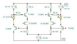
To me it´s an elegant way of directly applying the drain-source reference voltage. (An old British? idea).
Please note I did not say you do, that was addressed to Lineup.I never talk loosely.
To me it´s an elegant way of directly applying the drain-source reference voltage. (An old British? idea).
Attachments
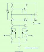
Here's that Halcro circuit in an easier to understand diagram.
They've used CFPs for the subtractor inputs to boost their gain, linearity and input impedance. They have then cascoded these with Q3 & Q4, referenced to the input emitters via V1. Then a second cascode with Q5 & Q6, this time referenced to the pos supply via V2. Q9 & Q10 form a current mirror that feeds the VAS amplifier, Q11, in turn cascoded by Q12. C1 is the miller cap.
They've used CFPs for the subtractor inputs to boost their gain, linearity and input impedance. They have then cascoded these with Q3 & Q4, referenced to the input emitters via V1. Then a second cascode with Q5 & Q6, this time referenced to the pos supply via V2. Q9 & Q10 form a current mirror that feeds the VAS amplifier, Q11, in turn cascoded by Q12. C1 is the miller cap.
Attachments
Some great replies folks; thanks so much for the interest!
Precisely the goal, since the emitter voltage approximately represents a buffered base voltage.
Taken under advisement, with my gratitude! Are you suggesting issues which might not show up in simulation, i.e., due to small, unpredictable parasitics such as trace inductances?
This is sensible enough, as is the following.
The Miller effect can be regarded as a pole whose frequency is proportional to source impedance (assuming constant C-B [Miller] capacitance), correct?
I definitely concede that there's nothing most of us can do with a transistor that would be for the first time, and had no expectation of a new invention. Our art is manifest in the bigger picture, I feel; how we each utilize various implementations to form stages with the best possible overall profile of compromise, is what is (may be) novel.
I think this sort of addresses my previous question, but I'm left wondering how the drive impedance to the upper transistor would be caused to increase? Something I'm still missing?
We're cool.
Thanks; comments below...
Appreciated the recap for clarity. Parts of these are kind of similar to where I was thinking of going with this in the first place. I'm puzzled in trying to realize the benefit of referencing 'supplemental' cascode stages (Q5, Q6; 15, 16 in other diagram) to the supply rail (certainly not questioning application to Q12; 29 in other diagram). Seems this will not work toward PSRR, but would in fact decrease 'statistical reliability' by increasing component count, all other things equal. Perhaps just to make it a patentable concept?
Delightful insights, thank you!
darkfenriz said:Your circuit from example II is actually referencing collector voltage to emitter voltage.
Precisely the goal, since the emitter voltage approximately represents a buffered base voltage.
This is very nice circuit and should perform better than ordinary cascode from example I, but beware of oscillations! There are paths of feedback which may create a high Q oscillator at several MHz. This may need some experiments with layout, base resistors or even ferrite beads to tame it.
Adam
Taken under advisement, with my gratitude! Are you suggesting issues which might not show up in simulation, i.e., due to small, unpredictable parasitics such as trace inductances?
Tim__x said:When you have voltage gain, the miller effect never goes away. Whenever there is significant voltage swing on the collector relative (remember voltages are always differential) to the base, you have the miller effect.
Ignore ground, just look at the voltages and currents actually presented to the transistor and you'll see a CB stage is no different than a CE stage.
This is sensible enough, as is the following.
All a cascode does is let you move the miller effect to a different transistor. It lets you pick a faster, lower capacitance transistor without much penalty, and it's makes it easier to drive the miller affected (
The Miller effect can be regarded as a pole whose frequency is proportional to source impedance (assuming constant C-B [Miller] capacitance), correct?
Your idea (which I am sorry to say, like most other ideas is not new) will likely increase linearity. It's hard to predict what it'll do for speed, it'll reduce the remaining miller effect on the lower transistor, but it will also increase the drive impedance to the base of the upper transistor lowering the pole produced by the miller capacitance.
I definitely concede that there's nothing most of us can do with a transistor that would be for the first time, and had no expectation of a new invention
. Our art is manifest in the bigger picture, I feel; how we each utilize various implementations to form stages with the best possible overall profile of compromise, is what is (may be) novel.I think this sort of addresses my previous question, but I'm left wondering how the drive impedance to the upper transistor would be caused to increase? Something I'm still missing?
Lumba Ogir said:acoustixman,
Please note I did not say you do, that was addressed to Lineup.
We're cool.
Appreciated. I've seen some pretty good old british ideas.To me it´s an elegant way of directly applying the drain-source reference voltage. (An old British? idea).
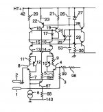
traderbam said:Halcro published this input stage in one of their patents. Seems to employ much of what has been said already.
Thanks; comments below...
traderbam said:Here's that Halcro circuit in an easier to understand diagram.
They've used CFPs for the subtractor inputs to boost their gain, linearity and input impedance. They have then cascoded these with Q3 & Q4, referenced to the input emitters via V1. Then a second cascode with Q5 & Q6, this time referenced to the pos supply via V2. Q9 & Q10 form a current mirror that feeds the VAS amplifier, Q11, in turn cascoded by Q12. C1 is the miller cap.
Appreciated the recap for clarity. Parts of these are kind of similar to where I was thinking of going with this in the first place. I'm puzzled in trying to realize the benefit of referencing 'supplemental' cascode stages (Q5, Q6; 15, 16 in other diagram) to the supply rail (certainly not questioning application to Q12; 29 in other diagram). Seems this will not work toward PSRR, but would in fact decrease 'statistical reliability' by increasing component count, all other things equal. Perhaps just to make it a patentable concept?
Delightful insights, thank you!
The drive impedance to the cascode is increased by the output impedance of the added emitter follower. On reconsideration, there is an added impedance, but it is driven in counter-phase, it should actually reduce drive-Z to the cascode at low frequencies, while increasing drive-Z at higher frequencies when the emitter follower gain falls off.
Being now at least second order before any parisitic poles are taken into account, it makes darkfenriz' comments on stability all the more important.
I know, every time I think I've invented some topology it turns out someone did it thirty years before I was born!
Being now at least second order before any parisitic poles are taken into account, it makes darkfenriz' comments on stability all the more important.
I definitely concede that there's nothing most of us can do with a transistor that would be for the first time, and had no expectation of a new invention.
I know, every time I think I've invented some topology it turns out someone did it thirty years before I was born!
Tim__x said:The drive impedance to the cascode is increased by the output impedance of the added emitter follower. On reconsideration, there is an added impedance, but it is driven in counter-phase, it should actually reduce drive-Z to the cascode at low frequencies, while increasing drive-Z at higher frequencies when the emitter follower gain falls off.
Being now at least second order before any parisitic poles are taken into account, it makes darkfenriz' comments on stability all the more important.
So if I were to try to culminate an analysis here...
I'm thinking it would be beneficial to prioritize the following:
(Q1 - VAS): Maximize hFE: low voltage, high gain.
(Q2 - cascode): Minimize C-B capacitance, high gain best.
(Q3 - moving reference buffer): MAXIMIZE GAIN-BANDWIDTH PRODUCT, with hFE at second priority, to target maximum linearity and flat spectrum with stability.
Sound about right?
Utilization of compensation (Miller) feedback on Q3 begins to seem like an option for keeping things tidy in the semiconductors (push reference toward signal ground at high frequencies), but of course the whole reason I'm pursuing this is quick transient response, so there'd be a limit to how low of a pole frequency would be appropriate before I might as well not have bothered trying to get fancy in the first place... Surely the simple cascode takes it 90% of the way to ideal (in cascode terms, namely acquiring the benefits of reducing Vce variance on Q1, especially in the VAS) so maybe I'm just chasing excess cost for reduced certainty of stability.
Ahhh, for the intrigue of audio!
Tim__x said:I know, every time I think I've invented some topology it turns out someone did it thirty years before I was born!
Of course, it's nice to find something that others don't currently recognize as a 'better idea' every now and then, and then find that it IS a better idea. The brave quest for unlikely perfection!! Audio design and prototyping has been my fiercest and most satisfying challenge to date, and life has NOT been otherwise boring. Fun stuff we do!
Re: accompanying schematic
acoustixman
No matter if you intend to debate this or that in this ahere topic,
any talk of any issue on circuit topology can benefit from some general observations.
We have a saying in my country, and I know there is a saying for this in english, too
People are very, very clever and precise and mathematically correct (at least in the abstract sense, not necessarily taking in account for the final practical implemention for their amplifiers).
At the same time we see these highly advanced analog mathemacal wonderboys
shows a astonishing lack of understanding of the context where these semiconductor formulas will have to work in.
Audio design, for real,
is about understanding your Sound System as a whole.
This is the general context, the environment, all these transfer functions HAVE TO DEAL with.
One complex system.
amplifier detail > amp stage > amplifier > PCB layout >
> power supply > source signal unit > load sound producer unit (speaker)
acoustixman
I am not questioning your use of cascode
Neither have I told I am 100% against use of cascoding.
Because I have seen & understood the benefits, even in practical applications.
------------------------------------------------------------------------------
Lineup said: I do not often use cascode.
The few times I use it, is 9 times out of 10 in the VAS.
It is very much dependent on the actual transistors, voltage and currents used,
if there is a real benefit of using cascoding.
At least to justify the increased complexity and deal with drawbacks.
------------------------------------------------------------------------------
acoustixman
In every topic there are 4-5 people that really debate.
And post their thinkings.
There are maybe 100-200 just reading and following the debate.
It is these normal diy people, who seek knowledge here, that I often concerns with.
I mention there are drawbacks with cascoding.
Some things get worse and adds new issues to your amp stages.
darkfenriz
has understood this, as we can see by his reservations.
nevertheless he knows also the benefits of cascoding very well.
Even maybe better than you and me
all these Trees, make me realize I am in One Forrest
and I know for a fact Our world is not only a lot of trees.
There are things outside This Forrest ... too
Strange at it is .. with all these intelligent people barking up their own little one tree,
this needs to be pointed out .. over and over .. again and again.
We need to know where we are,
even if we can not see our world,
at every One Moment in Time.
Lineup Audio Systems Lab
lineup said:I do not often use cascode.
The few times I use it, is 9 times out of 10 in the VAS.
It is very much dependent on the actual transistors, voltage and currents used,
if there is a real benefit of using cascoding.
At least to justify the increased complexity and deal with drawbacks.
--------
Regards
acoustixman said:Thanks all for the replies;
lineup: I didn't intend to be debating the use of the cascode topology itself. Agreed; like all practical circuit implementations it has real-life limitations and represents a form of compromise (rail voltage loss margin being the greatest in my opinion). These limitations do not generally include bandwidth or linearity in my experience.
--------
Thanks again all, and happy listening!
acoustixman
No matter if you intend to debate this or that in this ahere topic,
any talk of any issue on circuit topology can benefit from some general observations.
We have a saying in my country, and I know there is a saying for this in english, too
We see this sometimes also in audio and circuits.You can not see the Forrest
because there are so many Trees in sight!
People are very, very clever and precise and mathematically correct (at least in the abstract sense, not necessarily taking in account for the final practical implemention for their amplifiers).
At the same time we see these highly advanced analog mathemacal wonderboys
shows a astonishing lack of understanding of the context where these semiconductor formulas will have to work in.
Audio design, for real,
is about understanding your Sound System as a whole.
This is the general context, the environment, all these transfer functions HAVE TO DEAL with.
One complex system.
amplifier detail > amp stage > amplifier > PCB layout >
> power supply > source signal unit > load sound producer unit (speaker)
acoustixman
I am not questioning your use of cascode
Neither have I told I am 100% against use of cascoding.
Because I have seen & understood the benefits, even in practical applications.
------------------------------------------------------------------------------
Lineup said: I do not often use cascode.
The few times I use it, is 9 times out of 10 in the VAS.
It is very much dependent on the actual transistors, voltage and currents used,
if there is a real benefit of using cascoding.
At least to justify the increased complexity and deal with drawbacks.
------------------------------------------------------------------------------
acoustixman
In every topic there are 4-5 people that really debate.
And post their thinkings.
There are maybe 100-200 just reading and following the debate.
It is these normal diy people, who seek knowledge here, that I often concerns with.
Even if the those obesessed with cascoding make it look that way.They should know,
that only by adding cascode in every possible place in their amplfiers
will NOT Bring their audio sound systems into NIRVANA of listening pleasure.
I mention there are drawbacks with cascoding.
Some things get worse and adds new issues to your amp stages.
darkfenriz
has understood this, as we can see by his reservations.
nevertheless he knows also the benefits of cascoding very well.
Even maybe better than you and me
Well, you see,You can not see the Forrest
because there are so many Trees in sight
all these Trees, make me realize I am in One Forrest
and I know for a fact Our world is not only a lot of trees.
There are things outside This Forrest ... too
Strange at it is .. with all these intelligent people barking up their own little one tree,
this needs to be pointed out .. over and over .. again and again.
We need to know where we are,
even if we can not see our world,
at every One Moment in Time.
Lineup Audio Systems Lab

Probably lesstraderbam said:Lineup, what are you talking about?
More coffee required?

- Status
- This old topic is closed. If you want to reopen this topic, contact a moderator using the "Report Post" button.
- Home
- Amplifiers
- Solid State
- Cascode Buffers