Does that mean you consider the test unreliable even though it is based on repeated measurements? In any case I will repeat the distortion measurements for comparison.That was just a untested board layout exercise from a long time ago.
I'm very wary of making untested changes to circuits as I've been caught out with that in past. You see something later and wonder why on earth you did it that way at the time... you alter something... and sometimes it doesn't go to plan.
What I can say is the amp in its original form has proved itself over 2 decades now and those that have constructed it have all rated the sonics very highly. Unless you drive the amp hard into clipping the effects noted here, as it comes out of hard clipping, are really a non-issue (imo). It is way outside the normal performance envelope.
Enjoy the musicthat is what it was created for.
Yes agree.No not at all, the test isn't unreliable, it is what it is
Let's wait for the rest .
I can't do this today,I'm in the bed 🛏️due to gastroenteritis.
Thanks Mooly,I hope too.Oh heck, hope you soon feel better. And I see we have a do-dah for bed, lol.
I can't afford this.
These solutions work by shorting R10 to the negative supply rail which reduces the Vbe of Q4 under extreme operating conditions.Hellow thimios.
VAS is a 6mA CC on the positive side, but the negative side is a Darlington transistor that is actively on.
In this case, saturation causes excess charge to build up in the OPS.
This can also be seen from the fact that the recovery time from saturation on the negative side is much slower than that on the positive side.
View attachment 1115535
When the OPS is strongly saturated in this way, oscillations can be induced, such as by the drop in ft, when returning to the active state.
It is recommended to limit excessive driving during saturation on the negative side.
I propose three types of proposals.
from left
Adding a Baker clamp diode. A small signal Di with a withstand voltage of 100V or more is required.
There is a penalty of increased distortion due to the voltage dependence of the interelectrode capacitance of Di.
Adding three series small-signal diodes to limit the voltage on R10
Adding a small-signal transistor to limit the current in Q5
All of them are just a few extra parts, so you should be able to try them out easily.
View attachment 1115537
I suggested reducing R10 from 6k8 to 4k7 which reduces Q4 vbe by more direct and simpler means that avoids hacking the pcb or redesigning this to include additional components.
If I had observed the 'scope shots thimios has posted I would be asking Mooly to to provide simulations to see how THD, IMD, and stability plots stack up along side his subjective views on performance.
I think it likely that the malfunction thimios showed would have been made worse than it would have been without the dc servo op.amp
Last edited:
I have some mental difficulty to believe that in music a square or even a sine wave at 20kHz and at 25V could work in a tweeter. What kind of music could produce that ? Maybe some special music for the bats ? If it does not change at all the very good sound produced by Mooly's amp, I will probably add the three diodes as said by the good man mason_f8. Thank you mason_f8 !
This amplifier is the best I have heard until now, and it did become my main amplifier home. There is no way to change that.
@thimios : I hope too that you feel soon better my friend.
Best regards
rephil
This amplifier is the best I have heard until now, and it did become my main amplifier home. There is no way to change that.
@thimios : I hope too that you feel soon better my friend.
Best regards
rephil
I think it likely that the malfunction thimios showed would have been made worse than it would have been without the dc servo op.amp
Just for interest... this is with a servo and transformer power supply. You can see the start-up behaviour and why I always mention that the speaker delay is such an important part of the amp.
It's a tough one to simulate with a power supply and a servo. The 20kHz output comes in at the end of the trace. It would take all day if it was applied at the start.
And the 20k output when massively overdriven. The 8 ohm load makes no difference apart from limiting maximum Vout.
And with no servo and fixed rails.
This amplifier is the best I have heard until now, and it did become my main amplifier home. There is no way to change that.
Thanks for the kind words
That means a lot.I have looked at this latest update and drawn up a SPICE file for square wave signal testing at 10kHz. From what I can see there should be no issues with this circuit even with a 2uF test capacitor in parallel with 8R. There could be a faulty component, something in the layout or the assembly process or the 'scope test set up. I missed a trick with the constant current set up around Q3 sorry, mea culpa, and the fact that Q7 and Q6 have some voltage gain.
Attachments
Last edited:
I have looked at this latest update and drawn up a SPICE file for square wave signal testing at 10kHz.
Thanks @mjono. What I see in your simulation looks just like the real version to me.
Which reminded me that someone in the LT thread... and apologies to whoever it was as I can't remember the name... posted a brilliant squarewave generator that starts at zero volts. I saved the file at the time. Open both together and you can copy the generator to your file.
This is with the servo.
If anyone is interested then they can change the value of TR in the model for 2N5551C to 1US.
Thanks James, that's something else to try at some point
Attachments
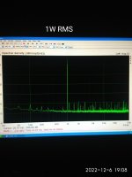
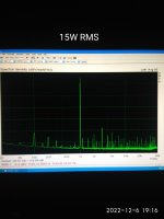
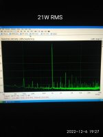
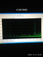
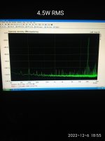
IMD test for the modified board.
Α significant improvement for the modified board ,of both Distortion and Intermodulation Distortion is discernible.
However, the measurements remain to be verified by simultaneously measuring both the original and the modified board.
Α significant improvement for the modified board ,of both Distortion and Intermodulation Distortion is discernible.
However, the measurements remain to be verified by simultaneously measuring both the original and the modified board.
Attachments
Last edited:
No comments about measurements?Have you not listened to it yet
Please give me the time,a lot of projects on the same time isn't an easy job🐢
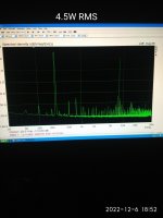
Hi Mooly,you can compare numbers with the previous unmodified posted #1335 already.The raw numbers look fine to me. Strange the distortion decreases at higher output (1w vs 4.5w).
I've nothing to compare it against seeing just your numbers
I do the same way to all amplifiers that I have built.
All are posted here in diyAudio.
I can post links if it is any interesting.
Distortions decrease at higher output is something common for all amplifiers that I have measure.
I don't know if it is a result of low R divider parallel to R dummy parallel to sound card line input z.
Last edited:
It might pay to check the LT1357 servo op.amp how is this decoupled from the supply rails? Has this been set up in accord with datasheet recommendations etc.The raw numbers look fine to me. Strange the distortion decreases at higher output (1w vs 4.5w).
I've nothing to compare it against seeing just your numbers
- Home
- Amplifiers
- Solid State
- My MOSFET amplifier designed for music