Re: No Monsieur Gaetan. not to remove them
Hello Carlos
OK, I understand.
If somebody want to keep that diode protection to protect the 10 ohm resistor, how about placing a 10 Pf cap across those diodes if they detect radio frequency ?
Bye
Gaetan
destroyer X said:Remove them ONLY and IF you find problems.
I have listened reports, from other friends, that those diodes detect Radio Frequency... also i had problems once, and recently i had problems even into the simulator.
It is difficult to me to explain things in English.... keep them in place IF you face some problems.... remove them, as the first suspect, if you have unstabilities.
I had....but..they are very protective to the 10 ohms resistance... and when that resistance burns the problems are very big...so... diodes are nice thing... they are needed...they are a nice solution...they are a clever solution..but they have shown problems.
regards,
Carlos
Hello Carlos
OK, I understand.
If somebody want to keep that diode protection to protect the 10 ohm resistor, how about placing a 10 Pf cap across those diodes if they detect radio frequency ?
Bye
Gaetan
Attachments
May work Gaetan, good idea...also ferrite beads my help
Have to try... the next time i face that i will try your capacitor.
I am not very sure if will work..because capacitor where you have radio frequency detected... sometimes the capacitor can increase the detection, including it's own capacitance to the diode inter electrode natural capacitance.... this is something to try
thank you.
regards,
Carlos
Re: May work Gaetan, good idea...also ferrite beads my help
Hello Carlos
Yes it may happen, the cap radio signal may need to be sent to ground. Or maby small inductor in serial with the diodes.
Bye
Gaetan
destroyer X said:
Have to try... the next time i face that i will try your capacitor.
I am not very sure if will work..because capacitor where you have radio frequency detected... sometimes the capacitor can increase the detection, including it's own capacitance to the diode inter electrode natural capacitance.... this is something to try
thank you.
regards,
Carlos
Hello Carlos
Yes it may happen, the cap radio signal may need to be sent to ground. Or maby small inductor in serial with the diodes.
Bye
Gaetan
Yes.... into my imagination may work, but also can produce opposite effect
Dear Gaetan, mon ami, mon frère... pour vous.
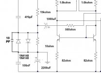
radio frequency normally enters when find tune circuits... arrangements of capacitances, resistances and inductances presented into parts and boards.... it is a matter of luck sometimes... see the sketch.
The input parts, if their arrangement produces an inductor in parallel with a capacitor, there's a tune circuit... a ressonant pair... depending the capacitor value and he inductor value you will tune some frequency.
This tuning will depend of the circuit "Q"... something alike gain..also the slope of the bandwidth captured by the tuned circuit... this bandwidth (frequencies that can enter) can be explained by the sketch, showing two types of reception.... low Q and big bandwidth and high Q and small bandwidth...and this can appear combined too in many forms.
The diode uses to rectify the radio wave.... so.... separates the carrier from the modulation...that modulation is what can enters the circuit..something we cannot listen sometimes when modulated into frequency... when modulated in amplitude you perceive more easy the signal into the audio... the noises.
The diode, has a capacitance and inductance and resistance... all components have... normally not so big capacitance and not so big inductance and not so big resistance..but they can be understood by all those things together.... so.... may tune some frequency... if very small can be tuning cell phones or higher frequencies than that.... depends how close you are to the cell phones antennas... i have one 55 meters from my place.
And we have a lot of signals around to be picked... radio telephones... wire less telephone....electronic baby sitter... broadcasting stations... Radio Amateur... police car radios and some properties are protected by electrically powered fences that uses frequency generators too (oscilators)... and the fence is the aerial sending high power signal, as magnetic waves, into the surrounded air... and travells for miles away.
Inserting caps... inserting inductors..well.... we can make things even worst...but also we can tune another frequency that has not transmitters around...and this can work... deviating from the source of interference frequency.
We use capacitors to the ground into the input...but... depending the value...if smaller than 100 picofarads, can be more a problem than a solution..because associated with the board inductance into the input parts can produce the a tuned circuit, exactly into the broadcasting band..... 22, 27, 33, 39, 47 picofarads into the input represents "guarantee of problems"
Why?
Because the inductances values presented into the input parts and copper lines, together those values of capacitance we can install.. and also the capacitances presented into the parts to ground... and inter capacitance between parts, probable will reach frequencies that are used..so... frequencies that have signals around.. and they can enter the circuit.... facing a fast input transistor (differential) than the ship is made...a ship filled till the top with problems... those things are correlated into a formula... where enters frequency, capacitance and greek letter "P"...that is 3,14 .... because of that i dislike when people put radio frequency units (able to work into frequencies higher than 90 Megahertz).
Sound turns "arrested"... strange... without brigth...compressed...treble goes harshing... too much metalic... have some "squeak" sounds into the high frequency peaks... this can kill the amplifier sound!
Radio Frequency Interferences (RFI) do not recognizes borders, frontiers... it can be generated in other country, and even this way, enter your amplifier.
regards,
Carlos
Dear Gaetan, mon ami, mon frère... pour vous.
radio frequency normally enters when find tune circuits... arrangements of capacitances, resistances and inductances presented into parts and boards.... it is a matter of luck sometimes... see the sketch.
The input parts, if their arrangement produces an inductor in parallel with a capacitor, there's a tune circuit... a ressonant pair... depending the capacitor value and he inductor value you will tune some frequency.
This tuning will depend of the circuit "Q"... something alike gain..also the slope of the bandwidth captured by the tuned circuit... this bandwidth (frequencies that can enter) can be explained by the sketch, showing two types of reception.... low Q and big bandwidth and high Q and small bandwidth...and this can appear combined too in many forms.
The diode uses to rectify the radio wave.... so.... separates the carrier from the modulation...that modulation is what can enters the circuit..something we cannot listen sometimes when modulated into frequency... when modulated in amplitude you perceive more easy the signal into the audio... the noises.
The diode, has a capacitance and inductance and resistance... all components have... normally not so big capacitance and not so big inductance and not so big resistance..but they can be understood by all those things together.... so.... may tune some frequency... if very small can be tuning cell phones or higher frequencies than that.... depends how close you are to the cell phones antennas... i have one 55 meters from my place.
And we have a lot of signals around to be picked... radio telephones... wire less telephone....electronic baby sitter... broadcasting stations... Radio Amateur... police car radios and some properties are protected by electrically powered fences that uses frequency generators too (oscilators)... and the fence is the aerial sending high power signal, as magnetic waves, into the surrounded air... and travells for miles away.
Inserting caps... inserting inductors..well.... we can make things even worst...but also we can tune another frequency that has not transmitters around...and this can work... deviating from the source of interference frequency.
We use capacitors to the ground into the input...but... depending the value...if smaller than 100 picofarads, can be more a problem than a solution..because associated with the board inductance into the input parts can produce the a tuned circuit, exactly into the broadcasting band..... 22, 27, 33, 39, 47 picofarads into the input represents "guarantee of problems"
Why?
Because the inductances values presented into the input parts and copper lines, together those values of capacitance we can install.. and also the capacitances presented into the parts to ground... and inter capacitance between parts, probable will reach frequencies that are used..so... frequencies that have signals around.. and they can enter the circuit.... facing a fast input transistor (differential) than the ship is made...a ship filled till the top with problems... those things are correlated into a formula... where enters frequency, capacitance and greek letter "P"...that is 3,14 .... because of that i dislike when people put radio frequency units (able to work into frequencies higher than 90 Megahertz).
Sound turns "arrested"... strange... without brigth...compressed...treble goes harshing... too much metalic... have some "squeak" sounds into the high frequency peaks... this can kill the amplifier sound!
Radio Frequency Interferences (RFI) do not recognizes borders, frontiers... it can be generated in other country, and even this way, enter your amplifier.
regards,
Carlos
Attachments
Correct dear Nordic...big capacitors will force to tune a very low frequency..so...
circuit will NOT pick radio frequency.
But also...if too much big...will be a filter of treble to ground.
The same happens with the input electrolitic condenser or input capacitor...it also filters the treble too, depending the value and the base resistance.... the input capacitor and the base resistance are in series to the ground...so... a filter!... the passive RC filter.
Because of that, people use to put the smaller possible capacitor into the input..not to have losses of high frequencies there.
regards,
Carlos
Attachments
Still much work to do, especialy since Carlos published at least one updated schematic in the time it took to get this far... also still needs the output resistor, and need to accommodate the cap on the input which increased 1000 times in value since the first publication.

Sorry dear Nordic.... i am always trying, doing, searching..sorry for that
When young, mother use to say i had a flea inside my pants.
Now a days, very fat, i do not move to much..but brain is always working, i use to wake up during nigth to take notes of things i conclude over nigth... when left neuronium is sleeping the rigth one is waken up...the third and last one is always thinking how to put the other two ones to figth...as he wants to the the only one.
I am sorry to say.... if Precision.... three transistors are needed dear Nordic..three pairs.... was error..... could create problems..there are dangerous speakers and some amplifiers "destroyers" too.
For Sakis, the Greek warrior, the amplifier has to accept shorts into output ( 2 ohms or less) having square wave into the input, overdriven..he is professional in public adress and he needs something huge...those folks can kill the HRII in flash using two transistors into the output....and worst... Sakis, if construct, will make it bigger, better and will put higher supply voltage too.
I would like to ask you dear nephew Nordic.
It is time to make some modifications..boards not ready..this one has only two output..so..will not be fine.... and also because of that, we have some time to do some tweaks.
I want to make this amplifier not only mine design and your board... i would like to have more from you on it.
Please tell me if you dislike some circuit, some subcircuit, some value, some current, some heat...if you prefer the output with coil...tell me what you would do with this schematic go make it more nice to you... and i will try to do it.... and fast!
If possible...of course... but i think you have possible ideas.
What is Pi?... is the Greek letter, the "P" letter ..... 3,14
regards,
Carlos
Important animals those ones.
Suck out condensers.... they "eat" noises the transistors can generate during switching.... when you drive the amplifier hard.
Those folks are needed..important.... very important..and they need to be from base to base... can go down the boards without problems..and also no problems to use links or jumpers....multi links, serial links, on board links, aerial links...no problems to sound..problem will be the omission..during the distortions, into clipping, the sound will be worst.... so... you will have to reduce volume..will loose power, will loose dinamic, will not use the amplifier with it's whole capacity to send huge current to the speakers.... They are one of the 5 features that made this amplifier better than HRII.... see that HRII use this condensers before the stop resistance... this one use directly into the bases.
If you ask me what i have done to increase sonics... i will anwer you... 5 things, and one of them is this one.
Sending you suggestion. about board.. image ballance is connected to human evaluation of beauty...cars have both side the same.... things are simetrical in our world...we feel this more pretty than assymetrical things..... please... try to ballance the image..if possible..only if possible.... and the more you could.
Take some time... will not waste time..for sure will not be... visit Delta Audio... watch Jan Dupont (our forum friend) and see the quality of image into the boards...he is the Master... he is the best we have into our forum...so...into the audiophile world..he is the Master, the best, the King of perfection into boards.
He said once:
"I have lost many hours into the basement working hard to make nice boards"
So.... go to the basement nephew..and spend some time on it.
Precision II is a little different...has current sources for driver transistors...more parts, more zener diodes and more two transistors...and have other modifications too...but this board can be the start for the Precision II... and this one we can do for sale into the Internet with profit for us.... cannot show schematic for free... schematic was sold..not for public use, but i have the reserve of dominium... i can use it..so..we can use it Partner!
CCS, power CCS into Driver transistors were used by Electrocompaniet... was there i found the idea... and i introduce it to my amplifier..yes... i made some clone of that circuit but parts, values are different... the CCS to the drivers has not patent and no copyrigth to Electrocompaniet (if they still exists)
Never switching off drivers is the feature of the Precision II... this result excelent sound... see how Roender made...very clever..gênius...he used high current into the drivers...do you know why?...heheheheh..not to have switching..waste current?... Not.... quality of sonics..big advantage.
Roender is the man...watch him with care.... and copy his ideas..the man is good..he is very good...real good.
regards,
Carlos
Attachments
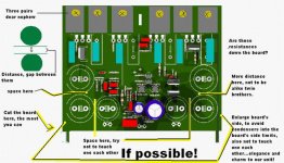
Dx Corporation Chairman sent internal communication
ordering to put condensers inside the board..having excess of board...boards larger than condensers...also not to touch condensers with condensers..and to try to put simetrical images into the boards.
Chairman have not called counsil because bad mood... wife said he cannot eat more chocolate!
bah!
Carlos
Attachments

Yes, you must get off the chocolate and carbonated cooldrinks, eat fruit, being as overweight as you are poses the same threat and life expectancy as someone with prostate cancer... it is very serious, and she does it because she loves you...
I worked onthe front side a little bit again
I worked onthe front side a little bit again
Better, much better Nordic.
But please, use three pairs into the output.
a little more large boards too...one milimeter more than the condenser will be nice..it is strange when the condenser is bigger than the board.
Nice one...thank you dear nephew.
Yeah.... she is rigth... and i am kidding...not with bad mood really.
regards,
Carlos
About the last image you have published Nordic
My opinions.
The circuit is fine... transistors, board sides and distance between condensers not perfect into my mind.
I think you can do it a little better.... of course...if you agree
Also, we can put the VBE multiplier transistor, the servo as you use to call it, into the heatsink, exactly into the middle horizontal line, where the power transistors are.
regards,
Carlos
Attachments
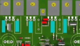
I know this is very common, very standard, everybody does this way
Maybe because looks very good.
Maybe because obvious positions...maybe to avoid wiring.... do not know..but almost all amplifiers are constructed simetrical way.
I am showing in this image, something the old Australian amplifier already use.... i think the SC480 or something alike that.
Do you like?
Yes.... hard to put more two transitors into the board and copper lines into the heatsinks... maybe not possible.... so... let the way it is possible.
Yeah...no innovation, nothing new...the same old style.... but imagine if we decide to chance powder... the last development, the maximum point was to make grains and the powder is without smoke.... to make new, as reached the best point.. the maximum..we can go back... to make it no grains and burning with smoke once again?
regards,
Carlos
Attachments
Re: My seven years old Volkswagen needs some repair
I usually work on my cars on sundays, but more for fun hehe..
170horses is'nt enough anymore, i need like 400hp or something in my old 1984 celicasupra.. http://dsl.mine.nu/galleri/7m/bilen.jpg
Nice to see your work on the amplifiers is not standing still..
Oh about the parts prices, me living in sweden some parts are actually very much cheaper to order from the usa..
Like buying ngk platina sparkplugs here in Västerås is a god damn joke..
I've been working on a kind of amp too, but I cant let go of the complementary design although I know it's probably not the best way for me to go.. been experimenting with local feedback from the vas to the diff amp in different amounts, I find for me a little vas feedback produce's the sound I want.. ( or lack of sound)..
I recently found that my recent idea is a little like LT1794 opamp , i don't know wether to be sad or happy about that..
http://dsl.mine.nu/ampsida/schematics/ you can see a lot of cräp here not all versions work hehe, it's the superbasimp I'm concentrating on now.. or somthing almost like that one, god damn schematic change allt the time..
anyway.. looked at your schematic and I cant really complain about much.. about the vas protection, I have tried to blow them too but failed..
but I'm using bd139 as vas and it can take 0.5ampere through the base and that's prettu much imho, when using ccs, well Its probably going to work but me not using ccs now made me worred about that so i put 80ohm's or 100ohms with a capacitor in parallell, needed that because the former version i did with ccs needed soooooo daaaamn much calibrating before it was good balanced..
.......destroyer X said:ball bearings, oil, steering box terminals, fuel tank floating piece,alignment, fuel injection cleaning, spark plugs substitution and more...more...more...more.
135 dollares will be the cost.
Brasil is wonderfull...in other country you may pay 2 times more.
My car is the same as the white one you see in the picture bottom.
I will answer, each one of you in a couple of hours.
regards,
Carlos
I usually work on my cars on sundays, but more for fun hehe..
170horses is'nt enough anymore, i need like 400hp or something in my old 1984 celicasupra.. http://dsl.mine.nu/galleri/7m/bilen.jpg
Nice to see your work on the amplifiers is not standing still..
Oh about the parts prices, me living in sweden some parts are actually very much cheaper to order from the usa..
Like buying ngk platina sparkplugs here in Västerås is a god damn joke..
I've been working on a kind of amp too, but I cant let go of the complementary design although I know it's probably not the best way for me to go.. been experimenting with local feedback from the vas to the diff amp in different amounts, I find for me a little vas feedback produce's the sound I want.. ( or lack of sound)..
I recently found that my recent idea is a little like LT1794 opamp , i don't know wether to be sad or happy about that..
http://dsl.mine.nu/ampsida/schematics/ you can see a lot of cräp here not all versions work hehe, it's the superbasimp I'm concentrating on now.. or somthing almost like that one, god damn schematic change allt the time..
anyway.. looked at your schematic and I cant really complain about much.. about the vas protection, I have tried to blow them too but failed..
but I'm using bd139 as vas and it can take 0.5ampere through the base and that's prettu much imho, when using ccs, well Its probably going to work but me not using ccs now made me worred about that so i put 80ohm's or 100ohms with a capacitor in parallell, needed that because the former version i did with ccs needed soooooo daaaamn much calibrating before it was good balanced..
- Status
- This old topic is closed. If you want to reopen this topic, contact a moderator using the "Report Post" button.
- Home
- Amplifiers
- Solid State
- Dx Precision, finally released... now debugged and better than HRII