
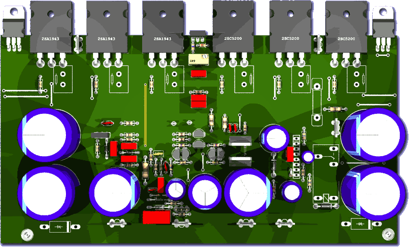
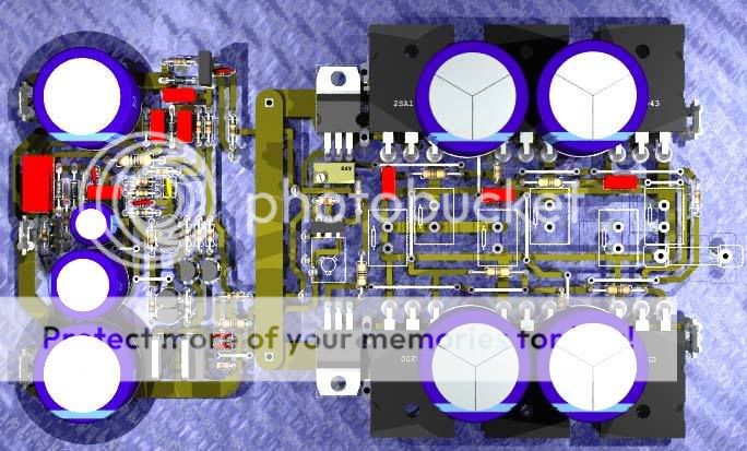
PCB 10cm x 20cm
Ok Carlos said the drivers need to go on the main heatsink or they may explode!!!!!!!
Still have some madness to sort out on the trace side, well its more like one of those puzzles where all the pieces fits except one. Also I would like to test the SPLIF topology wich will be a switch, you will loose some dissipation power, so not for full volume, but it will isolate the amp from evil feedback from the speakers.
GREG: the horizontal BD139 renders upright.... any help?
I like it...but the board result very big
Maybe dual in line... into heatsinks alike the ones you have may be good.
I suggest you to think in such a way, because the future Precision II, the one is already designed and tested, will use two extra transistors, and each one of them will dissipate 5 watts.
So...near future, output pairs will jump to 4 pairs and we gonna have 5 TO220 also into the heatsink.... drivers, 2 extra transistors and VBE multiplier.
And i am thinking to use rail regulators for the input supply... this will use more 2 TO220.... this will jump to 7 TO220.
Because of that, to use the board design you have, only including more parts, i will need to be big and constructed this way.
regards,
Carlos
Attachments
Precision is not ready... boards beeing finished soon
Precision II already made and tested....to go between april and june.
The Legacy will be released into 2008 Christmas.... already designed and will be constructed and tested into the first days of this next year... will be under test whole year.
regards,
Carlos
Precision II already made and tested....to go between april and june.
The Legacy will be released into 2008 Christmas.... already designed and will be constructed and tested into the first days of this next year... will be under test whole year.
regards,
Carlos
Attachments
Those boards are going to be HUUGE!!!!!!!!
But i will not let them confuse me into makeing the current boards more compromised than needed.
I am starting to form some preferences for the design, the most likely for a number of reasons is a split board with input and drivers section and section with the outputs. Wich can be a one long inline unit or 2 units split PNP and NPN. Haveing them in sections allows one to do just one section in doublesided, at much reduced cost compared to a full size doublesided board.
Those large boards will have to go doublesided to regain some sanity. If I could think of a way to thermaly link SMD 2n5401s, I would even go there....
The other option may be a one-piece butterfly layout like you suggested for the next version, but the little man in the back of my head says it will be even larger....
Lots of things we need to keep in mind... Stray inductances, stray capacitances, things keeping me awake at 3 in the morning in bed. Starting to change layouts in the morning while my first kettle is still boiling.
I will still keep trying for a bit, sometimes art is created by just throwing buckets of paint at canvass.
Nordic said:GREG: the horizontal BD139 renders upright.... any help?
Sorry Nordic I couldn't find a quick answer for this. The only 3D model for a TO126/TO225 device is vertical. Also, there is no vertical model for the TOP3P device.
Both of these can be found in user.inc and will require some additional code to add the vertical/horizontal options. I will do this one day as I need these options for myself.
regards
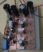
This board is wonderfull too... i like it.
But i do not like the solution of power transistors under the board... this way you made, that difference you made as you place the transistor screw free to attach is better, as you can screw them into the heatsinks from upper board side.
This solution, or the last solution are fine to me...also another third option will be good too...i think you are very developed, now a days very skilled related to make boards and to find good solutions to the problems you face.
I do not like, this is personal, very subjective, big condensers over some amplifier board.... i feel that condensers, the big ones are for supplies...they bother me a little, alike a Transatlantic ship parked on my garden...i have the feeling that something is strange..something is out from the correct place....but i can fix that into my own boards, as i hate those big ones i can put smaller ones and ready...problem is the big circle that remains showing something strange..ahahahaha...now the strange thing is my small condenser there!
This seems to me fashion those big ones.... supply is near.... 20 or 30 centimeters of wire do not make the supply electrolitic condenser detached from the amplifier board.... it is so small resistance, that cable...so small that the adition of big condensers into the boards (more than 2200uf) will be an overkill...in the reality, the colectors should have only 100n.
Those condensers are included into the design because forum majority of people believe that condensers soldered into the board, very near the output transistor colector makes a difference.
You can test, swith 100 N and 10000uf and see the difference you have.
Some decisions are politically correct, or nice..... not to produce scandall, but there are many myths that need some A to B comparison, made by dear constructors to feel the real thing.
Doctor Self came with this idea in his book... despite now a days i love Doctor Self...i would use his hat and a "T" shirt with his name with pride... despite that i do not agree with that need if you do not have "remote supply"...with 1 meter cable from the supply to the power amplifier.
In my schematic you will see big condensers....why?
Because there's no supply posted for this amplifier.... imagine someone using rectifier to the input circuits supply and 100uf of filter to each rail...only that..... because of that possibility, of not good supply going to the amplifier, i decide to install big condensers into the board...not because big condenser into the boards are really needed, in special near power transistor colectors when you have a good supply feeding your amplifier.
Having good supply.... not too much long cable from supply to power amplifier...anything around 470uf or 1000uf in parallel with 100n will decouple and work fantastic.
regards,
Carlos
I like the board too, but...
Greetings and thanks for playing around with this. Does that mean you are going to tackle the big amp too? Count me in for a board set if you do.
The butter fly arrangement may get too wide for common heat sinks if you did that, but like Carlos I think would be better if the transistors on the heat sink could be removed (to replace failed ones for example) without having to unsolder all six (to remove the board to get to the screws attaching the to the sink). Would it be possible to have the front end circuitry between the output transistors to keep the width of the heat sink narrower - just wide enough to accommodate the width of three transistor (plus bias servo)?
Where does the bias compensating transistor go? Is it the one shown between the left most power transistors? If so how would it be installed on the heat sink and replaced?
I could not guess what is the yellow/green band to the left of the power transistors is? Seems like there might be board space to be saved if it does not have a specific purpose. How big is the board as you have it now?
This is what I want for Christmas. As the board seems to have spare space could we please have sufficient width for Wima MKP capacitors between resistors and other parts. And bigger (than the HRII board) solder pads and room for 8 mm pitch resistors at least.
Beste groete
Re: I like the board too, but...
Hi,
No need to configure it that way. It could be screwed through the board into the heatsink (see pic). Soldered on the bottom side.
Lose some board real estate, but I now believe it's worth it. No worries about breaking a lead out, everything held tight, safe and sound.
Looks good too.
Francois G said:
...but like Carlos I think would be better if the transistors on the heat sink could be removed (to replace failed ones for example) without having to unsolder all six (to remove the board to get to the screws attaching the to the sink).
Hi,
No need to configure it that way. It could be screwed through the board into the heatsink (see pic). Soldered on the bottom side.
Lose some board real estate, but I now believe it's worth it. No worries about breaking a lead out, everything held tight, safe and sound.
Looks good too.
Attachments
Yes François, i will be happy to see this one produced to Mars release
You know those things delay...so.... Nordic is starting to make his traditional excelent job.
And we will feel happy to accept your order.
Already have 5 orders, a great thing because the boards are not even ready and people have trust...this is excelent...means we gonna be happy once more...you, Nordic a lot of folks and me too.
regards,
Carlos
.....................................................................................................
Dear MJL21193
Your construction is fine, there's no problems about that to be made into our home.
But to order boards, from board's factories, area, size, are things very important that can make huge different into the final price.
Your method, despite nice, would be the first thing you would change after collect board factories price to order hundred boards for instance.
You see that there's are wasted, doing nothing, or...covering power transistors only...and this can be also annoying to some people that appreciate to see the "little soldiers" aligned on the board top or around the board.
It is not so easy when you need to make repairs..in the reality is not good to repair as you cannot replace a single transistors and have to dismount the whole thing...or have to remove all screws..and a lot of mess happens, that damn grease, thermal grease will make enormous mess into our lives...also insulators...will be a nigthmare...at least compared to other more simple, less sophisticated ideas, it is more difficult, more confused, less economic.
You see the area wasted...no one see transistors...only copper and screw... copper without function, that also will turn dark after some time pass, because of oxide (maybe you have painted with varnish to protect the copper, a very clever idea)
regards,
Carlos
Attachments
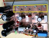
Also, dear friend, MJL transistors and 2SC also are very pretty units
Nice big hard Epoxi blocks, we will happy to see them.
People can see and say.... uow!... a lot of power units...this shows power... alike the smell makes the food better... the transistor quantity makes we feel the power with our eyes too.
See the image, the more traditional way to construct can produce around 20 percent of board area economie.
Thank you to offer us your suggestion and to explain us your point of view..almost good to individual home construction, not the best to group buy
regards,
Carlos
Attachments
Re: Yes François, i will be happy to see this one produced to Mars release
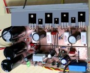
Hi Carlos,
Yes, the price of board production is high, and the extra square inches costs money, BUT I think it's worth it. We are building audiophile equipment, right? Not in competition with Sony.
If it's a couple of dollars more is that too much?
The copper above the drivers/outputs is a ground plane and the bigger, the better (I've heard). Proven too (for me). That amp does not make a sound when running - no hiss, no hum.
I have coated it with lacquer before assembly. Brown copper wouldn't bother me anyway, look antique but I can't see it inside the case.
Keep up the good work!
Merry Christmas and Happy new year!
destroyer X said:
But to order boards, from board's factories, area, size, are things very important that can make huge different into the final price.
Your method, despite nice, would be the first thing you would change after collect board factories price to order hundred boards for instance.
... copper without function, that also will turn dark after some time pass, because of oxide (maybe you have painted with varnish to protect the copper, a very clever idea)
Hi Carlos,
Yes, the price of board production is high, and the extra square inches costs money, BUT I think it's worth it. We are building audiophile equipment, right? Not in competition with Sony.
If it's a couple of dollars more is that too much?
The copper above the drivers/outputs is a ground plane and the bigger, the better (I've heard). Proven too (for me). That amp does not make a sound when running - no hiss, no hum.
I have coated it with lacquer before assembly. Brown copper wouldn't bother me anyway, look antique but I can't see it inside the case.
Keep up the good work!
Merry Christmas and Happy new year!
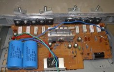
Re: Also, dear friend, MJL transistors and 2SC also are very pretty units
Like This? It's beautiful!
destroyer X said:
Nice big hard Epoxi blocks, we will happy to see them.
Like This? It's beautiful!
Attachments
Well, I don't have those T /L brackets you guys seem to screw your transistors into.... All my boards so far have been soldered underneath ... and the transistor is the filling in the sandwitch.
So I'll be damned before I design something I can't use myself
You can solder transistors over board if you have L Bars.
The gold bar is a kind of placeholder as I need to think about the GND connections, I thought I will have 2 GND stars, one for front, one for rear, both connects to chassis ground star.
I still think haveing all transisotrs on one side of board is better, as it allows a greater selection of heatsinks..., as long as your sink is about 20cm long it will work.
Relating the capacators, I chose to allow for two capacitors in parallel so that you can use lower values, but almost all the larger value 100V caps from about 1000uf are common in the sizes I used.
I am not sure I agree on the impact of caps close to the transistors.
After I followed Grahams advice on adding large caps right to the transistors in the original DX, there was a HUGE improvement. Not subtle, not something to argue about, it was concrete fact. So much so, that despite poverty, I now save up and buy those large caps, they are worth every last cent.
On the topic of caps, Am i right when I say if the ripple rateing is higher than what the load demands on a single cycle (which I think we can consider a ripple too...) can draw down, the Voltage on the cap should stay unaffected...?
Also I nearly fell on my back the other day when a friend showed me his 10000uf caps, they were only 100V, but probably 8cm across.. and 15cm high, absolutely giant... according to him, they are "better" than the regular "small" ones...
Yes...nice "soldiers" MJL...good that one!
We are all different, and also the same... there are small differences about taste, aesthetics and those things.
No problems to think different, because will match thousand of folks personal needs...they are different too.
Some dollars more cannot make big difference into rich countries...but here, 1 dollar can represent a nice toasted chicken, ready to eat, hot and made alike a barbecue..and you can loose that one because you have spent one dollar more into a board.... 2 dollares is a nice 600 grames (more than a pound) can filled with delicious Nestlè Chocolate.
1 dollar more for a board.
1 dollar more for the car motor oil
1 dollar more for the hamburger
well...those things may represent 500 dollares into the end of the year....this means you have lost a wonderfull television...you could have bougth that one with that money lost.
The most lucky folks here receive payment upper than 1000 dollares each month.... some Executive goes higher than 2000 dollares...the President owns 4000 dollares....and the minimum payment is 160 dollares (and was 50 dollares 7 years ago).
regards,
Carlos
.....................................................................................................
The condensers do not need to be 100 Volts dear Nordic.
This increase cost and the worst, increase condenser diameter because the insulator is thicker.. between metal sheet you have inside the condensers.
That voltage we have written outside the condensers are the "maximum voltage guaranteed"..... this seems it will not explode with some volts more.... a big under rated...under kill, the factories does to make them reliable, safe, guaranteed.
63V condenser units (I think this number is standard...or at least was a standard value into the recent past) can hold more 20 percent... and this is because mains voltage can have this variation too... almost all electronics are made to tollerate plus and minus 20 percent..and this is considered "normal fluctuations".
Some schematics show this to you.... and you can see written there... voltages can differ 20 percent.
This means the 63 volts condenser can work with more than 75 volts without explode, leak or something alike.
This way, as i have used this all my electronic life ...going to 46 years using condenser that you may understand as "under rated" and i do not remember some of them exploding.
I had many damaged because me, stupid, have inverted them..but i cannot remember one exploding because of overvoltage on them.
So...they really accept much more....my amplifier that use 39 volts supply (the ones i have), are using 35 volts condensers.
The Precision can use 63 volts condensers...they are not fat.
No problems if you decide to use 100 Volts....for sure mine will be 63 volts because i do not like those whales over the board...my problem...my solution.
Boys!... we have gigabytes of data of myths into our heads... a lot of myths planters use to seed us with those things...and into our communitty those myths have room to survive, to increase that turn into reality....if we could make some defragmentation into our brains, for sure myths will be painted coloured and if deleted will create a lot of space into our brain hard disks.
I really think, professionals may laugh about us because our beliefs, and also because of that they "introduce", deep and hard those "unobtanium" cables into our...... and we deserve that.
regards,
Carlos
We can aggree to dissagree ")
Now another question...
Why do we use a seperate supply for the front...? can voltage not be dropped like in HRII using zeners and cap multiplier?
It would certainly reduce build cost drastically, probably 30% or more...
I'm bussy looking at a 200W into 8R amp, at the moment... the thing is running 70V rails from front to back... input 2sa1084 outputs MJL21193... it has 4 pairs... not a big step up from precision.
Studio 350 Power amp , Everyday Practical Electronics, Oct, Nov, Dec, - 3 part article...
I think I will go with the onesided transistor boards.... with some modification...
It just has so many more options it allows for... especialy now that I am looking at foto's of such a layout.. will even reasonably accept those round can transistors using short wire leads...
Can more easily be fitted to lower profile cases etc... another probably money saveing feature...
- Status
- This old topic is closed. If you want to reopen this topic, contact a moderator using the "Report Post" button.
- Home
- Amplifiers
- Solid State
- Dx Precision, finally released... now debugged and better than HRII