Hi,
I'm in the process of making a buffer between pot and power amp.
- I shall work with my 100k-log Alps as well with 10k Relais-ladder
- stable
- work effortlessly on reasonable loads
- exhibit a certain fancyness
- sound good
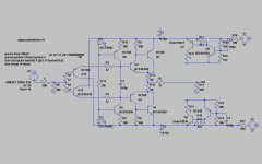
The circuit shows where I am at the moment.
With shown source- and ouptut loads it sims 0.0003% THD.
However, with any other transitor models than shown this number gets worse, so the models might not be accurate.
This is somewhat dependent on the source load, but independent for output loads of 500R and above. Q3/Q4 run at 8mA, Q12/Q13 run at some high 10mA, which helps distortion going down.
I might end with beefier q3/Q4 in the end as well.
The voltage reg. is another area of endless playing...
I might stuff some protection diodes, but this is for later.
Soundwise it has strong and defined bass, and (to my surprise) soft and nice trebles. It plays effortlessly.
My perfboard layout shows some issues with spontaneous oscillations sometimes which need to be solved prior to extensive listening, though.
Rüdiger
I'm in the process of making a buffer between pot and power amp.
- I shall work with my 100k-log Alps as well with 10k Relais-ladder
- stable
- work effortlessly on reasonable loads
- exhibit a certain fancyness
- sound good
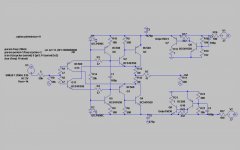
The circuit shows where I am at the moment.
With shown source- and ouptut loads it sims 0.0003% THD.
However, with any other transitor models than shown this number gets worse, so the models might not be accurate.
This is somewhat dependent on the source load, but independent for output loads of 500R and above. Q3/Q4 run at 8mA, Q12/Q13 run at some high 10mA, which helps distortion going down.
I might end with beefier q3/Q4 in the end as well.
The voltage reg. is another area of endless playing...
I might stuff some protection diodes, but this is for later.
Soundwise it has strong and defined bass, and (to my surprise) soft and nice trebles. It plays effortlessly.
My perfboard layout shows some issues with spontaneous oscillations sometimes which need to be solved prior to extensive listening, though.
Rüdiger
Attachments
Re: Update
Hello Rüdiger, interesting circuit. Supply is around 21V if I am correct? What's the max output before distortion starts to rise appreciably?
Jan Didden
Onvinyl said:0.000008% THD

Hello Rüdiger, interesting circuit. Supply is around 21V if I am correct? What's the max output before distortion starts to rise appreciably?
Jan Didden
Hi Jan,
yes, around 20V. This is to reflect my bench-psu, I'd go for 24V sooner or later.
for 1 Volt AC it's 0.000008%, for 2 Volts it's 0.000018,
3 -- 0.000029
4 -- 0.000042
5 -- 0.000057
6 -- 0.000074
8 -- 0.000118
12 - 0.00024
20 -- 0.000716
25 -- 0.0012
30 -- 0.0022
Above 34, where it's 0.079, it clips.
These numbers make me nervous, somehow to good to be true.
I'm fiddling with a perfboard for this second one, until now I get green fog on my scope, bad oscillations, even the DC points won't follow the simulation.
Well, there are issues. It oscillates with low input impedances, and the bad news is, it's the same in reality *and* in the sim. Even the Frequency is close. You can tame this a bit (and half the distortion as well) if you chose 2sc1775/2sa872 as the input pair.
I would have liked to check with jfets there, but I don't get them biased properly.
It shall excell after a high-impedance VAS or anything, but I can't think of a way to have a pot in front of it and keep the extraordinary numbers.
Rüdiger
I would have liked to check with jfets there, but I don't get them biased properly.
It shall excell after a high-impedance VAS or anything, but I can't think of a way to have a pot in front of it and keep the extraordinary numbers.
Rüdiger
Gordy said:You can use a constant impedance attenuator. They have constant input *and* constant output impedance.
I do not have web references, however if you look up variable Bridged-T attenuators you should find something. They are used in pro-audio and RF work.
Here you go:
http://www.ibiblio.org/obp/electricCircuits/Semi/SEMI_1.html#xtocid18468
Refer to Bridged-T attenuator near the bottom of the page. Design the impedance at whatever level you desire for your circuit. You can calculate it for 5k, 10k, 20k, etc.
Vary R6 and R7 at the same time (use two gang rotary switch and resistors). The input and output impedance stays constant as the attenuation changes.
You can buy ready-made attenuators here:
http://www.shallco.com/attenuators.html
They say:
" "T" and Bridged-T Circuits
Both "T" and bridged-T attenuators provide accurate adjustments in signal level with zero insertion loss. Increments from 0.1 dB to 2 dB are standard with ranges of 10, 20, 30 and 45 steps in most impedances. In addition to parameters and the devices listed in our online catalog we can provide custom designs for special applications. All devices are manufactured with precision film resistors of ± 1% accuracy and are housed in shielded enclosures. All terminations are solder lug type. Bridged-T type devices are lowest in cost and are equally as accurate as the "T" for all but the most stringent applications. Our applications engineer can recommend the best and most economical device for your application. Standard impedances are 600 ohms but others are readily available. All units are equipped with detents. "
I am sure that they could supply you with something at whatever impedance you need. However it might be more fun and cheaper to build it yourself.
Thanks, Gordy,
that was new to me.
It does not work with this ckt, however.
With different T-values, it behaves completley different, from gorgeous numbers (as low as 0.000001% THD) to modulated signal (think AM) up to wild oscillations, all with the same constant impedance but different attenuation values.
It strucks me.
Rüdiger
blu_line said:This thing is damn fast.
Add a cap over b-c @ Q1 and Q2 !
grtz
Simon
been there. It helps a bit, but even 1nF can't cure it completly. Heck, you can finetune, but only for a fixed input network.
Rüdiger
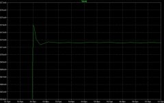
With the shown pot setting (50k/50k) I get optimum results with R13/R16 = 40R and R5/R6 = 210R, giving Q1/Q2 around 3.7mA.
We're at 0.000001% THD then, sim, of course.
It does not get better lower than 40R nor does it get better with CCS in place of R5/R6.
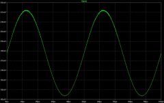
With a pot setting of 99k/1k (the latter referenced to ground) we get the oscillating related dist., reading 0.19% (see below)
For the moment, I'm short of ideas.
Rüdiger
We're at 0.000001% THD then, sim, of course.
It does not get better lower than 40R nor does it get better with CCS in place of R5/R6.
With a pot setting of 99k/1k (the latter referenced to ground) we get the oscillating related dist., reading 0.19% (see below)
For the moment, I'm short of ideas.
Rüdiger
Attachments
The more I look at this, the more I like it. Simple and elegant. No specific ideas on the oscillation, but to oscillate some part of the circuit has to satisfy Barkhausen's criteria- a gain greater than one and a phase shift of 360 degrees at some frequency. If you can figure out exactly where in the circuit this gets satisfied, the cure is usually more obvious. I hate output networks, but I've seen arrangements where the R13/16 combo becomes a more complex arrangement that includes a capacitive divider to tailor the loading a bit at higher frequencies.
I meant the two output transistors, simple emitter followers. Your "compo" isn't easy to get working well, do I hear but I have no personal experience of such output stage.Onvinyl said:...Besides, I wouldn't exactly call your design 'conventionally' ...
Hi Rüdiger,
you might want to try loop-gain probing (see \LTSpice\examples\Educational\LoopGain2.asc) to deal with the oscillation. Probably you have too little phase margin in one or both of the feeback loops -- via the collectors of Q12/13. Two identical loop-gain probes must be inserted in the emitters of the output darlingtons, and responses can be looked at indivually or summed together. I'll try to recreate your circuit and the problem, and maybe the solution.
- Klaus
- Status
- This old topic is closed. If you want to reopen this topic, contact a moderator using the "Report Post" button.
- Home
- Amplifiers
- Solid State
- Jung/PMA Line-Buffer