I thing you have encounter the same problem than me.
After many many experimentation (more capacitance on the PS, shielding of transformers, moving the mechanical ground around ect...) i thing that i have a hint.
I replaced the feedback wire by a shielded one, grounded at one point (starground) and my FC100 is now dead quiet on the channel with this shielded NFB wire.
Maybe this wire pick up some hum by induction from the 1000uF caps that surround it. In my FC100 these caps are very low ESR and the ripple on the supply probably induce big current in these caps and surrounding copper, and this hum ( buzz in fact )was not equal on the two channels.
Denis
I doubt it is the difference in transformers, since the channels have much different results.
I think it is layout. Sheldon, I cringed a bit when I saw your wires spread out all over the place in your pics. I couldn't make out the wiring in the small pics to make any recommendations, though.
The wiring did look very different between the channels. You should twist PS supply and return leads together, where possible.
As to use of shielded cable for the feedback, you need not "star" ground the shield at one end. There is no signal in the shield. RF shielding is better with MORE ground connections, not less.
pooge said:I doubt it is the difference in transformers, since the channels have much different results.
I think it is layout. Sheldon, I cringed a bit when I saw your wires spread out all over the place in your pics. I couldn't make out the wiring in the small pics to make any recommendations, though.
The wiring did look very different between the channels. You should twist PS supply and return leads together, where possible.
As to use of shielded cable for the feedback, you need not "star" ground the shield at one end. There is no signal in the shield. RF shielding is better with MORE ground connections, not less.
Actually, they are wired the same. The layout is identical. One channel is upside down in the final assembly, but everything for that channel is the same as the other, including wire length.
The picture on the previous page looks messy, because there are a bunch of clip leads connected. The white wire you see on this page, just connects the two star grounds. The power supply mains leads are twisted, but the others are pretty short. I can try twisting them too, but again, layout is the same each side. If I can't sort it out, I'll open it up and provide a better picture. One thing I do know is that it is not the signal input wires, because the hum does not go away if I short right at board. It's not a preamp issue, as I can hear the difference with a speaker and shorted inputs.
I'll give the shielded feedback wire a try.
I get a little hum on both channels with the inputs open. But one is quiet shorted, or connected to a relatively low impedance source. The noise I get on the other is more of a higher frequency buzz.
Sheldon
pooge said:You have a wire connecting the two star grounds of each channel together???
That shouldn't be, especially with two transformer supplies.
Thanks. Was following this advice. http://www.diyaudio.com/forums/showthread.php?postid=1805482#post1805482
I couldn't hear a difference with or without. But it's easy enough to eliminate.
Sheldon
Sheldon:
I may have misread you scope photos. I didn't study them carefully. I looked at one and saw a left channel and right channel labeled. I didn't pick up that you had two photos like this, so I assume the green trace in each is a test signal??
Start eliminating issues if you haven't already. Power only one channel at a time (i.e., completely eliminate any possible interconnection between the channels). Swap power supplies between channels to see if anything changes.
I noticed a green wire from the channel on the left side of your photo in post #822 flying in air right next to, and around, the transformer. I'm assuming this is a ground wire, but can't tell. Hoping it's not picking up transformer charging pulses.
Run any ground and power supply wires externel to the board along the chassis surface instead of wildly through the air away from the chassis. I'm a bit concerned about the closeness of the transformers to the boards, and their orientation. The transformers have an outer shield band. Are they connected to PS ground? Try reversing the leads on the transformer primary. One direction will give less ground current. Check this by separating the PS ground from chassis, and connecting ammeter between the separated ground points.
Check all your heat sink insulators. Make sure they are insulating properly.
Edit:
To make this clearer, lift the safety wire from your power supply cord off the chassis, and measure the current between the chassis and the power cord ground wire when each channel is powered alone. Then, measure the ground current with the hot and neutral leads with the transformer primary reversed. Choose the orientation that offers the least measured current. Do this for each channel powered alone.
pooge said:I may have misread you scope photos. I didn't study them carefully. I looked at one and saw a left channel and right channel labeled. I didn't pick up that you had two photos like this, so I assume the green trace in each is a test signal??
Yes. White trace is output.
pooge said:Start eliminating issues if you haven't already. Power only one channel at a time (i.e., completely eliminate any possible interconnection between the channels). Swap power supplies between channels to see if anything changes.
Powering channels separately makes no difference. By swapping power supplies, I assume you mean front end supplies. I'll try that later, if other things don't solve it.
pooge said:I noticed a green wire from the channel on the left side of your photo in post #822 flying in air right next to, and around, the transformer. I'm assuming this is a ground wire, but can't tell. Hoping it's not picking up transformer charging pulses.
That's just a clip lead for testing. Post 827 shows close the final set up. The small twisted pair is the input wiring. It is sensitive to placement, when the input is open. So I position it for minimum hum in that state. Shorted, or with source connected, it doesn't pick up hum.
pooge said:Run any ground and power supply wires externel to the board along the chassis surface instead of wildly through the air away from the chassis. I'm a bit concerned about the closeness of the transformers to the boards, and their orientation. The transformers have an outer shield band. Are they connected to PS ground? Try reversing the leads on the transformer primary. One direction will give less ground current. Check this by separating the PS ground from chassis, and connecting ammeter between the separated ground points.
Check all your heat sink insulators. Make sure they are insulating properly.
The power and ground wires are against the chassis. The only ones not that way are the front end DC outputs. I can run them too against the chassis. It will look better that way, but, again, same configuration for both channels.
Yes, transformers are close, but not much I can do with this chassis. Amp two will be laid out differently. The transformer shield wire is connected to the chassis, which is connected to earth. It's the green wire next to the transformer in the upper right, post 829.
I'll test out the ground current issues a little later. Gotta go walk the mutt.
Sheldon
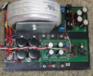
Here's a more detailed pic of the wiring.
The green thing between the 4 smaller power supply caps, is a film capacitor that connects the main star to the chassis (green wire going to bottom center transistor mounting screw).
The only other thing that is not self explanatory, is the small red/black twisted pair. Those take power from one rail to the relay for the soft start circuit. Not much current draw there, and I have checked the system with those disconnected - no effect on hum.
Leakage from the transformer should be primarily along the center axis, which is over the power supply part of the board, so I don't think this should be too much of an issue. Again, one channel only, affected.
Did replace the feedback lead with a shielded wire. That didn't do it.
Sheldon
edit 2: Couple other bits of info. I'm not using an output inductor. And; Both the "good" and "bad" channel sound about the same with the input open - probably mostly 120Hz. But when a source or shorting plug is used on the "good" side, noise drops to virtually nothing. On the "bad" side, the noise stays the same level, but increases somewhat in higher frequency components".
3. Also tried a different front end supply. No change.
Attachments
Thanks for all the suggestions folks. I went back and simplifies somewhat. I removed the front end ground lift. I got rid of the shielded feedback connector. I found that neither were helpful, and just make things messier. I connected just a fine guage wire for the feedback connection, but on the bottom of the board to R24 - just because it's easier to get at. I left the front end ground connected between c10,11.
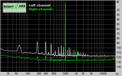
Redid the measurements, but properly set up the card this time. I think Mihai will be more pleased with the outcome. Right channel is still just a tiny bit noisier than the left, and a touch more second harmonic. But, the hum is only audible if I stick my head all the way inside my 100dB horn. So completely inaudible just a foot away. The actual dynamic range is larger than the graph makes it appear, as the card cannot take anywhere near full power, even with an attenuator on the output of the amp.
Left Channel
Attachments
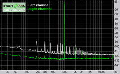
Are those field induced hum spikes on the left channel? Is there some more proximity to something than to the right channel?
I have seen in my projects that the strongest emission point with toroidals is the secondary exit points. Try to rotate if you have some slack while measuring and see if something changes. The different level and front to back distance of toroid mounting can be giving some more filed to one side in a different manner than to the other?
I have seen in my projects that the strongest emission point with toroidals is the secondary exit points. Try to rotate if you have some slack while measuring and see if something changes. The different level and front to back distance of toroid mounting can be giving some more filed to one side in a different manner than to the other?
Attachments
Salas said:Are those field induced hum spikes on the left channel? Is there some more proximity to something than to the right channel?
The two channels are layed out exactly the same. Just one is inverted relative to the other when assembled so that I could make the case a little narrower.
Ignore the Left/Right designation on the graph. The signal is the white trace. The green trace is just the card loop back. Left channel is the first post, right is the second. This shows noise at -90dB, but it's actually lower, as I have to limit the input to the card. As measured on the scope, it's over 105dB down.
Sheldon
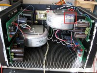
Edit 3: I see that you have outlined the exits for the front end secondaries. Next time I open it up, I'll rotate the transformer some and see if anything changes.
Aha. So its a common thing between channels. So your 0dB level isn't calibrated against 1V. What is the Voltage level of the signal spike on the graph? Of course SNR will go up with more output voltage delivery, but the noise floor level is the standard bottom. Try the rotations IMHO. If you improve it enough the amp will sound softer, deeper in 3D and more resolving. It seems adequately low, but its a gremlin. That comb extending far high is eating away resolution. Got to listen unmistakeably finer each time I have eliminated a not so obvious such problem. Its worth the chase. Beautiful aesthetics and construction BTW. Congratulations!")
Salas said:Aha. So its a common thing between channels. So your 0dB level isn't calibrated against 1V. What is the Voltage level of the signal spike on the graph? Of course SNR will go up with more output voltage delivery, but the noise floor level is the standard bottom. Try the rotations IMHO. If you improve it enough the amp will sound softer, deeper in 3D and more resolving. It seems adequately low, but its a gremlin. That comb extending far high is eating away resolution. Got to listen unmistakeably finer each time I have eliminated a not so obvious such problem. Its worth the chase. Beautiful aesthetics and construction BTW. Congratulations!
Signal level is about 200mV. Not sure that some of the noise isn't in my measuring system. I have a little preamp that I need to fix, then repeat the measurements.
Thanks for the compliment. I have a bad habit of trying to stuff too much into to little space. Might get away with that better with Mihai's R-cores.
Sheldon
I have this habit too... In my KT-88 I got rid of such stuff by using copper foil around the toroid, and grounded it. It may well be your driving electronics, of course. What I do is I use a 1:10 attenuator and I run the card at 1V RMS out through it. So it picks up some SNR and then drive the amp at 1W/2.83V at 8R. At about 100mV in, they normally hit the 1W if around 30dB gain. Also the output attn brings down computer psu wideband noise that rides the card's signal in many cases. That way I avoid preamp and I am not afraid of burning the dummy by mistake on output level. If you calibrate the card with a DVM, it will follow exactly what you type in as level. Use ARTA. Its free and has a detailed calibration menu, among other excellent stuff.
I didn't use the preamp on this test, just the card out, and attenuated the input. But I've had problems in the past with it. The pre, is just a little battery powered op amp, so I can feed it the full signal and have a nice low output impedance. Maybe I'll give ARTA a try, if I find the time to figure it out.
Sheldon
Sheldon
Salas said:Are those field induced hum spikes on the left channel? Is there some more proximity to something than to the right channel?
Pooge and Salas. Looks like the gremlins are indeed field induced from the transformer. It's not the wiring, per se, as I can push the wires around with no change in the hum/buzz. But surprisingly small changes in transformer orientation make a big difference. So, going to have to experiment, but it appears I can get rid of this background, even in this cramped chassis.
Sheldon
- Home
- Amplifiers
- Solid State
- RMI-FC100, a single stage audio power amplifier