Andrew
Point made - thanks. I will check the Jfets again.
I have noticed that I can pop fuses when i apply a short across the input (from a floating state). Did you ever get to the bottom of your problems?
Don't know if they fit, but I'd be tempted to use sockets for the JFET's, and test them in circuito.
I had problems blowing fuses. I had few incidences after I disconnected the star/earth DC connection, and replaced it with a 1uf foil cap (as per Mihai's suggestion). No problem after, inserting shorting plug or source connection.
Sheldon
I think Andrew may have had some blown fuses. Check the few pages before this post for detail: http://www.diyaudio.com/forums/showpost.php?p=1805690&postcount=788
I've since blown a few fuses probing around under certain conditions. It seems related to the meter characteristics, as some nodes react to the mV setting on my DMM, but not the regular DC setting (maybe related to probe capacitance). However, I've had no problems with external connections, since I switched from DC earth to AC earth.
Sheldon
Popping fuses
Hi Sheldon,
I appreciate your help...
I started the second channel a while ago and it looks like I missed a few posts during the build.
I am using quick blow fuses - I presume that you are too?
I will change my earthing over to AC and see how the fuses fare.....
Thanks
Hi Sheldon,
I appreciate your help...
I started the second channel a while ago and it looks like I missed a few posts during the build.
I am using quick blow fuses - I presume that you are too?
I will change my earthing over to AC and see how the fuses fare.....
Thanks

I have just realised that the input was not shorted when I took the offset measurement yesterday.
I have just shorted the input and the offset is 19mV.
Still pretty high. How well matched are R10 and R15?
Sheldon
Why do you have base resistors on most of the cascode bjts and not on the current sources? Are cascode devices more prone to oscillations and hence the resistors? Yet there aren't any base resistors on the cascodes to the input fets ?
Thanks.
In my experience, a low impedance voltage reference source connected in base of a CBmode bjt is very prone to produce spurious oscillations in that cascade device. Hence, there is no need for base stoppers in LTP cascade bjts, because the reference is a resistor and not a low Z Vref
Hi.
I'm very attracted to Roender amplifier and would very like to build it for a try.
Might I ask support about collecting parts for this beautiful amplifier?
I'm interested what type of emitter resistors is need to be used in that design. As far as I know this should be metal film, but it seems like such value isn't manufactured. Using wirewound type will seriously effect frequency response because of inherit inductance of such types.
Could you please tell me as well how to measure with DMM HFE for matching transistors sake?
Does this amp support 4 Ohm load?
May it be played from sound card output?
Can I use one transformer for output and one transformer for front end for two channels?
Can I use instead of NJL0281D/0302D NJW0281G/0302G devices and instead of BD139 BC640-016G?
What you guys thinking about using Toshiba TTA004/TTC004 instead of MJE15034/35? These are far better drivers I guess.
Likewise using Toshiba 2SK30ATM instead of 2SK170. The former one has far much better parameters than 2SK170. Just for convenience these transistors are listed in Toshiba General Catalog.
What it is needed to made a digital input for this amp.
Roender support will be very appreciated.
Roender would you tell me please a dimensions from far side of transistor to transistor (mounted under PCB) in rectangular manner just to know if PCB will fit onto my heatsinks?
Thanks.
Last edited:
voilla !
even if I was there - in first few pages of thread - later I probably had some other things to do")
just finished reading entire thread , that took me several hours , along with saving all files and pictures .....
roender - excellent work , but I must confess that brightest moments are pics where your son is ; I'm certainly biased , because my precious (5,5 yrs ) is sitting near me , looking at some H.C. Andersen stories ......
just short question ,regarding 25W A class version - just accordingly (OK - slightly) decreased PSU voltages for both input and output stage (+/-30) , and cranked bias (~1A3) ?
TIA
even if I was there - in first few pages of thread - later I probably had some other things to do
just finished reading entire thread , that took me several hours , along with saving all files and pictures .....
roender - excellent work , but I must confess that brightest moments are pics where your son is ; I'm certainly biased , because my precious (5,5 yrs ) is sitting near me , looking at some H.C. Andersen stories ......
just short question ,regarding 25W A class version - just accordingly (OK - slightly) decreased PSU voltages for both input and output stage (+/-30) , and cranked bias (~1A3) ?
TIA
Dear Roender
I have been reading this thread in the last couple of days, and I find it very interesting.
Please excuse my ignorance and stupid questions, but a couple of things puzzles me:
As far as I can see, if you use a device with a bigger die (like the NJL3281/NJL1302), the re of this device (assuming most of the re value comes from the die size and not internal leads aso) will be comparativly smaller. This again could lead to reducing the Re and you would end up the same B-biasing? A device with a die with double the current capacity would in my head equal two parralleled devices?? Am I missing somethig here?
The Cob would also be the same or less if you use fewer devices?
The other thing is the tempco issue. If you only use two output devices, you only have two internal diodes for tempco. But if you use a Vbe multiplier (the transistor NOT on heat sink) with the two diodes in series with the emitter, you would end up multiplying the tempco as well, so you end up the same place. Of course one set of NJL3281/NJL1302 will get sweat on their forehead , but this is only to make a point. You could probably get away with using two sets, haven´t done the calc. on that.
I have been reading this thread in the last couple of days, and I find it very interesting.
Please excuse my ignorance and stupid questions, but a couple of things puzzles me:
The classB crossover distortion is caused by variation in amplifier
output impedance with load current level at crossover point.
The optimal class B biasing for minimal crossover distortion requires
that R * gm =1 where R is the total ohmic resistance seen from the
emitter towards the base of one output emitter follower (one output
power BJT).
This resistance is : Re + re + Rs/(beta +1) where Re is the emitter
resistor on which you measure Vq, re is the parasitic internal emitter
resistance, Rs is the total base + source resistance
If Re is dominant, then the condition becomes gm * Re = 1 which means
Io * Re = Vt = 26mV. This is the usual condition (Self)
because gm = Io/Vt where Io is the bias and Vt is the thermal voltage
26 mV at room temp.
If Re is made smaller to avoid losses, then re may not be neglected in
front of Re and gmR=1 becomes gm ( Re + re ) =1
This means Io Re + Io re = 26mV and you are measuring the first term.
It is then normal that at optimum IoRe should be lower than 26mV.
In other words, if you want optimum class B bias and also as much as
possible Class A, you can not do it by increasing bias over 20 ...
26mV (20mV for 0302/0281 with 0.1ohm Re), voltage measured over one
emitter resistor. What other option do we have if we want more A
class? - to increase the number of output devices biased at optimum
class B current.
As far as I can see, if you use a device with a bigger die (like the NJL3281/NJL1302), the re of this device (assuming most of the re value comes from the die size and not internal leads aso) will be comparativly smaller. This again could lead to reducing the Re and you would end up the same B-biasing? A device with a die with double the current capacity would in my head equal two parralleled devices?? Am I missing somethig here?
The Cob would also be the same or less if you use fewer devices?
The other thing is the tempco issue. If you only use two output devices, you only have two internal diodes for tempco. But if you use a Vbe multiplier (the transistor NOT on heat sink) with the two diodes in series with the emitter, you would end up multiplying the tempco as well, so you end up the same place. Of course one set of NJL3281/NJL1302 will get sweat on their forehead , but this is only to make a point. You could probably get away with using two sets, haven´t done the calc. on that.
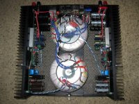
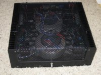
Ver. 2. Done with amps now. Speakers only from here.
Sheldon
Very business like. Cool. Got the harmonic field gremlin even down lower in this config I would suppose.
Very business like. Cool. Got the harmonic field gremlin even down lower in this config I would suppose.
Yes, a little lower. But it's hard to get to absolute zero in a stereo amp with transformers like this. I had to rotate them in a few iterations to get lowest value, and they interact somewhat. So it takes a few back and forth. Couldn't source transformers like Mihai's, which should have lower leakage still.
I'll probably dress up the front when I get an inspiration.
One annoying issue, is that I have one pair of opt transistors on one channel that bias at about twice the current as the rest. All the others are within a few mV. I tried to find some more to select from, but the main sources here (Digikey, Mouser) don't carry them any more, and I can't find any others that will sell less than 150. I used NJL3281/1302D. Anyone have a source outside the U.S.?
It doesn't seem to affect distortion, but are the hot pair likely to current hog if the amp is pushed hard?
Sheldon
Sheldon
To reduce (get rid of) this transformers hum issue you can try to dress them up in a permalloy shield.
Did you build RMI-FC100 MK II version or rebuild your first try?
Where did you find NJL, 2SA1360, 2SC3423, 2SK170 transistors? As far as I know only NJL types are available on Digikey and Onsemi.
As far as I know, Mihai has only published the original version. The hum is not much of an issue. Can't hear it unless my ear is within a cm or so of the diaphragm. Not worth a permalloy treatment.
I got the LSK from a DIY audio group buy, and the 2SA/SC from Bent. Got a few left, but probably not many matches.
Sheldon
I got the LSK from a DIY audio group buy, and the 2SA/SC from Bent. Got a few left, but probably not many matches.
Sheldon
As far as I know, Mihai has only published the original version.
Sheldon
MKII ver link: http://www.diyaudio.com/forums/soli...100-mkii-single-ended-folded-cascode-vas.html
- Home
- Amplifiers
- Solid State
- RMI-FC100, a single stage audio power amplifier