jacco vermeulen said:
Rare indeed, the ones found always look like roadkill.
A vegetarian rodent, so i gathered, and they appear to enjoy oatmeal a great deal.
(Nasty stuff, just the thought of youth oatmeal porridge days runs shivers down my spine.)
I swear I saw a haggis!

"According to one poll, 33% of American visitors to Scotland believe haggis to be an animal." http://en.wikipedia.org/wiki/Haggis
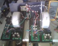
Down the home stretch. Got the parts back from anodizer and assembled everything up. At first, everything checked out fine. Then somehow during the course of testing/assembling, I probably shorted something. It's not the first time I've done that, and I have some spare components, so I was not too worried. Just gotta figure out what I cooked.
In originally assembling the boards, I followed Mihai's suggestion for sensitive speakers, and cut the trace, and lifted the front end supply connection to the main star with a 2.2R resistor. Whatever I'd shorted now, had overheated this resistor in the right channel, so it was now about 100R. I replaced it, and looked for any other obviously overheated components, but didn't see anything. When I powered back up, I noticed slightly more hum in this channel - about 1mV. The left channel reads at 0.1mV on my meter. Also, the offset on the right channel went to about +30mV, whereas the before it was less than 2mV.
I then checked various currents on each channel and got these readings:
R20 right- 1.343V, left- 1.344V
R19 Rch- 1.227 Lch- 1.227
R15,18 Rch- 1.281, 1.281 Lch- 1.278, 1.279
R16,17 Rch- 0.365, 0.367 Lch- 0.303, 0.305
R6,41 Rch- 0.567, 0.555 Lch- 0.747, 0.582 (note, R6,41 are 150R)
The only differences I see, are lower current for Q7,8 in the affected channel, maybe accounted for the the higher current draw for Q19.
Any suggestions on what to look for?
Sheldon
Attachments
Sheldon said:
In originally assembling the boards, I followed Mihai's suggestion for sensitive speakers, and cut the trace, and lifted the front end supply connection to the main star with a 2.2R resistor.
Sheldon
I must have missed this mod. Where are the details of this?
pooge said:I must have missed this mod. Where are the details of this?
http://www.diyaudio.com/forums/showthread.php?postid=1768772#post1768772
AndrewT said:post822 pic.
Is that a shorted turn around each of the toroids?
No, there's an insulating grommet on one end of the bolt.
Sheldon
Attachments
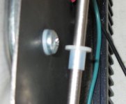
well thought out, you're a brave soul.Sheldon said:there's an insulating grommet on one end of the bolt.
AndrewT said:well thought out, you're a brave soul.
Thanks, but not that brave. The mains is fused at 5A to backstop me.
Sheldon
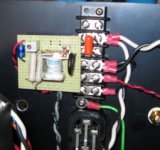
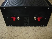
To get away with a smaller fuse, I added this circuit. It's a CL-60 in series with the line, with a relay switched by a transistor to short the device after a second or so.
Attachments
CrazzyAbtTubes said:Oooooh, I like tubes and all but this amplifier grabs my interest over any of the more recent ones I have seen.... I want to build one now!
If you're serious, PM me. I've got an extra set, including transformers. Seven stereo amps and two mono, not including the extra set. This one's a keeper but, realistically, I don't need two, and casework is the hard part.
Sheldon
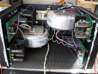
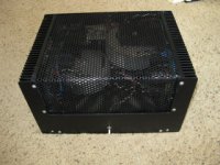
Sheldon said:Time to listen to music.
Under the hood.
Wow, very nice amplifier
congratulation!I'll look forward for listening impressions.
Cheers,
Mihai
I am more than serious Sheldon, this circuit interests me allot, especially for the fact that it operates in class "A" up to two watts because that is all I would need for home listening.
And those large outputs are the way to go for an reliable amplifier, this circuit would sound great with a 6AS7 preamp. I wish I had come across this circuit earlier because I am all ready in progress of rebuilding an LXI Sears amplifier, but I saved the schematic to the computer as not to forget about this amplifier.
As for that extra set of components, I will indeed PM you because I would put my LXI amplifier on hold to construct an amplifier as nice as this one...
Very nice construction job by the way.
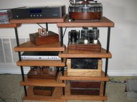
Sounds very nice. I've got it running 400-20kHz, on a multi amped system. http://www.diyaudio.com/forums/showthread.php?s=&threadid=69906&highlight= Can crank it up to very loud (when it's just me at home) and very clean. The compression driver and mids on the horn are crossed passively in this configuration. The FC 100 is driving the horn, and the horn system is corrected and crossed at line level with a DEQX to the woofers. The woofer system is described in the thread. I'm running one Symasym channel per woofer. They are the limiting factor in output for this. I've added Geddes foam to the horn and made some other mods to the cabinets, but basically as you see it in the linked thread.
I can run the tube amp at night for lower level listening and that nice glow, if I like (FC sounds very nice at low level too, and LED's are nice, but not as nice as tube glow). But if I wanna rock, gotta go with the FC.
Dressed up the amp with some Koa veneer, to soften the industrial tech look.
Sheldon
Attachments
Sheldon,
The strength of this amp is that it is capable of driving speakers full range, via passive x-over. This is because the 3 parallel output transistors will provide sufficient current to give you excellent bass response and CFP transistor to provide you a balance high frequency(I found this myself) response.
BTW the NPN and PNP output transistors are they just matched pairs(1npn and 1pnp) or they must be 3 matched pairs(3npn and 3pnp)? How did you make your amp? I ask this question before no one wants to give a response. Thanks.
ttan98 said:Sheldon,
The strength of this amp is that it is capable of driving speakers full range, via passive x-over. This is because the 3 parallel output transistors will provide sufficient current to give you excellent bass response and CFP transistor to provide you a balance high frequency(I found this myself) response.
Yes, I know. The way I'm using it is no challenge at all for this amp. At some point I want to try full passive crossovers for the system (except for subs). Actually, I started on this hobby several years ago with the idea to build a set of high efficiency speakers. Took so long to get the parts, that I started building amps (8 stereo, 2 mono, one phono, at last count). I think good passive crossovers are the hardest thing of all, and I've been procrastinating on that score. I'm going to tackle it over the next year.
ttan98 said:BTW the NPN and PNP output transistors are they just matched pairs(1npn and 1pnp) or they must be 3 matched pairs(3npn and 3pnp)? How did you make your amp? I ask this question before no one wants to give a response. Thanks.
The output stage, being a unity gain follower, I think that it's more important that all three npn are matched, and that all three pnp are matched, because this will affect the individual bias current. Of course, if you can match all 6, that is best, but I think it's less important to match npn with pnp. Mind you, I'm far from an expert, but maybe if I'm wrong someone will feel compelled to offer the correct answer.
BTW, the problem I had earlier with toasting the ground lift resistor between the frontend and output, was due to accidentally connecting the scope ground to the positive output. That resistor needs antiparallel diodes for the careless. Apparently I damaged Q10, because replacing it got everything back in line.
Sheldon
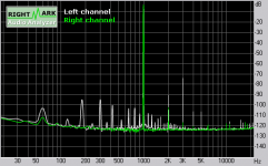
some measurements
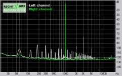
I get a slight amount of buzz on the right channel. It's very faint, but the left has none, and I wonder where the difference is. Seems the PSRR is slightly degraded in the Right channel. Could be I partially cooked something in all my adventures - would not be anywhere near the first time. It's not due to layout, as they are identical. Anyway, you can see the difference here:
Left Channel
Attachments
Rule out a ground loop between your amp and preamp (although that would more likely be a hum rather than a buzz.) Turn off your amp, disconnect one of the connects to one input channel, turn on amp, and check for buzz.
Edit:
Whoa. That's at 1 khz. Maybe getting some rf rectification???
Edit:
Whoa. That's at 1 khz. Maybe getting some rf rectification???
- Home
- Amplifiers
- Solid State
- RMI-FC100, a single stage audio power amplifier