For Sheldon and AndrewT,
Try removing the heatsink ground, or make sure the heatsink is not grounded to the centertap, also if using two seperate transformers and two seperate filter banks make sure the both star grounds are connected together for each channel with a heavy gauge wire, heatsinks should not be connected to star ground but may be connected to a chassis ground (not connected to star ground) which may be earthed. Grounding the heatsink in this style of High Frequency circuit seems to cause stability issues....
Colin
pooge said:So Sheldon, any listening impressions yet?
No. I wanted to test basic function and sink performance before doing the casework. I like to build a full stereo amp and then listen. It'll be a little before I complete the casework. I promised my wife that I'd finally finish the backyard garden and landscaping (which I have successfully avoided with various ruses for at least a couple of years now). So I have to put in at least some time there before I can sneak into the garage and cut and drill. Also, our little mutt recently died after 16 years so we just got a two year old dog that was destined to be put down. I think he was in a shelter because the previous owners couldn't handle him, and he is a bit of a project, though very sweet. After a week, we've got him halfway lease trained. Still, I have to give him a fair amount of attention until he's secure enough to absorb more challenging skills (like coming when called, learning how to be around other dogs, etc.).
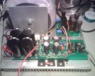
BTW, the sink that I show is half of the one I picked up at a surplus place. You were right that each half is only enough for two channels, if the emitter resistors are 0.1R. For this it's fine, as the rest of the casework will contribute significantly to the emissive surface. I'll give pics and measurements when done.
Sheldon
vynuhl.addict said:Try removing the heatsink ground, or make sure the heatsink is not grounded to the centertap, also if using two seperate transformers and two seperate filter banks make sure the both star grounds are connected together for each channel with a heavy gauge wire, heatsinks should not be connected to star ground but may be connected to a chassis ground (not connected to star ground) which may be earthed. Grounding the heatsink in this style of High Frequency circuit seems to cause stability issues....
Good to know. Each channel has its own transformer, though only one channel running now. I lashed it up fairly quickly, with a single rectifier. The earth and center tap and chassis ground G, at the opposite end of the board from the star ground, between P+ and P-) are both connected at the same point on the sink. I can route the center tap to G, and run a separate wire from there to the chassis/earth point, or are you saying no earth reference to the board?
Sheldon
vynuhl.addict said:Try removing the heatsink ground, or make sure the heatsink is not grounded to the centertap, also if using two seperate transformers and two seperate filter banks make sure the both star grounds are connected together for each channel with a heavy gauge wire, heatsinks should not be connected to star ground but may be connected to a chassis ground (not connected to star ground) which may be earthed. Grounding the heatsink in this style of High Frequency circuit seems to cause stability issues....
Good to know. Each channel has its own transformer, though only one channel running now. I lashed it up fairly quickly, with a single rectifier. The earth and center tap are and power ground G, (at the opposite end of the board from the star ground, between P+ and P-) and are all connected at the same point on the sink. I can route the center tap to G, and run a separate wire from there to the chassis/earth point, or are you saying no earth reference to the board?
Sheldon
Interesting that...if i remove heatsink ground from my amplifiers, they start to
produce noise... i will read the thread with calm...maybe you have something different there.....
Interesting suggestion Vinyl... got my interest because in my constructions.... grounded heatsinks is a rule that i have paid a lot when i forgot to follow.....but maybe you have some different problem in there....interesting folks..... will be a good reading to discover why that.... will be following your posts till the solution.
regards,
Carlos
In a dual mono amplifier, I used to connect every main starground to the case through 1...2uF foil capacitor.
When I said to connect the ground to the heatsink I mean to connect it at AC, not DC! Therefore, both amplifiers will have a common signal DC ground connected together at the signal source, once the signal source is connected")
When I said to connect the ground to the heatsink I mean to connect it at AC, not DC! Therefore, both amplifiers will have a common signal DC ground connected together at the signal source, once the signal source is connected
roender said:In a dual mono amplifier, I used to connect every main starground to the case through 1...2uF foil capacitor.
When I said to connect the ground to the heatsink I mean to connect it at AC, not DC! Therefore, both amplifiers will have a common signal DC ground connected together at the signal source, once the signal source is connected
OK, thanks.
Sheldon
I see... alike a shield...shield into metalic chassis
The way they use to do with Radio Frequency transmitters...they even use many capacitors in parallel..all them ceramics...1n, 4n7, 10n, 22n, 47n, 100n till they reach 1uf..when they used to stop.
Alike inner ground and outer ground.... beeing inner the star ground, the DC ground...and outer your method.
Nice and interesting...very effective.
Thank you,
regards,
Carlos
I've got a pair of mono modules assembled on the heatsinks and ready for the finishing casework. Everything looks good, with one exception. That is, I get around 5-6mA offset. I don't care much about the offset per se, but that, combined with 2-3mA variation in the individual output device current, makes it impossible to get all the output devices within the optimum 15-20mA bias current.
First, is this much of an issue?
Second, is there any convenient way to trim the offset?
Sheldon
First, is this much of an issue?
Second, is there any convenient way to trim the offset?
Sheldon
Attachments
Thanks Mihai,
One thing I noticed, is that the offset starts out negative, goes positive over the first minute, then gradually increases to the final level as the sink warms to steady operating temperature. Does that provide any clue as to where I might tighten things up, if any of the modules have higher offset?
Sheldon
Playing around a bit more, and blowing a stream of air from a tube, I found that the biggest effect was on the JFETs (as Mihai proposed). If I cool the input FET, the offset goes towards the negative. If I cool the other one, the offset goes more positive. Might see what I can do by swapping.
Sheldon
Sheldon
Sheldon said:Playing around a bit more, and blowing a stream of air from a tube, I found that the biggest effect was on the JFETs (as Mihai proposed). If I cool the input FET, the offset goes towards the negative. If I cool the other one, the offset goes more positive. Might see what I can do by swapping.
Sheldon
Bound them together with a thermal compound between
I got 0.2mV output offset.
The input pair are thermally coupled and bound with three turns 0.5mm diameter copper wire.
The output emitter resistors are matched to <0.5%.
Measuring output or bias currents through unknown or loose tolerance resistors is a complete waste of time and effort.
The input pair are thermally coupled and bound with three turns 0.5mm diameter copper wire.
The output emitter resistors are matched to <0.5%.
Measuring output or bias currents through unknown or loose tolerance resistors is a complete waste of time and effort.
AndrewT said:I got 0.2mV output offset.
The input pair are thermally coupled and bound with three turns 0.5mm diameter copper wire.
The output emitter resistors are matched to <0.5%.
Measuring output or bias currents through unknown or loose tolerance resistors is a complete waste of time and effort.
Right!
What a beautiful country you have, Andrew!
I've just returned from Highland. You must be proud with such a place!
Attachments


- Home
- Amplifiers
- Solid State
- RMI-FC100, a single stage audio power amplifier