pooge said:What is the maximum voltage drop the PSU regulator can do, so we can know the voltage range for acceptable transformers. Also, what is the minimum and maximum difference acceptable between the PS voltage delivered to the input stage and that to the output stage?
At least 5 volts between input and output
The front end PSU must deliver 5...8 volts over the output stage PSU in order to cover headroom lost by folded cascode bias voltages
Best regards,
Mihai
Attachments
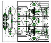
Re: layouts
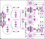
The labelling would be much more readable if you dropped the circuit pattern and left just the vias. Also, there was a tweak for C1 with the addition of a series resistor.
m2003br said:Hope this may help:
The labelling would be much more readable if you dropped the circuit pattern and left just the vias. Also, there was a tweak for C1 with the addition of a series resistor.
roender said:
At least 5 volts between input and output
Best regards,
Mihai
Are you talking about the regulator board here? If so, what is the maximum allowable input voltage?
pooge said:
Are you talking about the regulator board here? If so, what is the maximum allowable input voltage?
Yes.
The max input voltage? Don't know, never think about ... depends on how big the PSU heat sink is and SOA of the used CCS transistor.
With specified parts and 39V output voltage I wouldn't go over 55V input voltage
m2003br said:Mihai,
What you think about the use of a better and bigger resistor in the NFB (R24 - 22K)?
Thank you,
Marcos
If you think that using a bigger wattage resistor is better for the sound, go ahead, no problemo! I believe that there is some space on PCB for 1w RPM resistor but no more than that
roender said:It is possible to use other output voltages by putting other zener valuesbut don't forget that this is a shunt PSU. You have to modify CCS current in order to keep at least 10-15mA through PSU output transistors (MJL15034/35).
Happy Holidays,
Mihai
Thanks Mihai. And Thanks to all for the pictures. Makes the build a little easier.
Best Wishes to All,
Sheldon
roender said:
Roender,
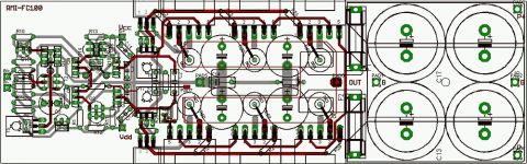
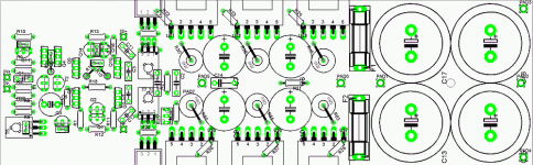
Sorry if this was already discussed somewhere on this thread, but I noticed in your parts layout for the PSU, you didn't picture the required jumpers between the banded ends of D1 and D3, or across the pads next to the base and emitter of Q7. Anyone taking the care to build this should recognize this, but I just thought I've give a heads up.
Also, the labels for Q4 and Q5 could be clarified. I can't even see Q4 in there, and Q5 is unclear which transistor is intended.
Also, I got to wondering if you have any suggestion for mounting the PS board, since there are no mounting holes. At first I thought you mounted it via the vias under the heat sinks, since all those heat sink vias need to be connected to ground/each other. But then I understand the three ground busses are connected together via the heat sinks pins soldered to those vias.
pooge said:OK. Do you set it at maximum or minimum resistance when starting up for the first time to set bias?
Put it at minimum when you'll first fire up the amp, then check the voltages over every output resistors. You should read something between 2 and 8mV. After that, slowly increase the voltage to 18-20mV and wait till heatsink will turn warm enough (one or two hours). Read again the bias level and readjust if necessary.
I must mention that heatsink should have at least 0.35 grdC/W in order to support such high level of power dissipation, around 37W per monoblock.
If you don't have a big enough radiator than increase all emitter resistors to 15 or 22mohm and keep the same bias voltage (18-20mV)
Happy building,
Mihai
Originally posted by roender
Put it at minimum when you'll first fire up the amp, then check the voltages over every output resistors. You should read something between 2 and 8mV. After that, slowly increase the voltage to 18-20mV and wait till heatsink will turn warm enough (one or two hours). Read again the bias level and readjust if necessary.
Glad I asked! In the Leach amp you start at maximum resistance. Since the primary failure mode in pots is an open circuit, any problem with thermal runaway if this happens? If so, it would seem prudent to put in a parallel resistor as discussed previously to limit maximum safe resistance.
Originally posted by roender
I must mention that heatsink should have at least 0.35 grdC/W in order to support such high level of power dissipation, around 37W per monoblock.
Can I make do with .375?
Originally posted by roender
If you don't have a big enough radiator than increase all emitter resistors to 15 or 22mohm and keep the same bias voltage (18-20mV)
If it is no work on your part, can you estimate the class A range using 15 and 22mohm resistors?
Thanks.
jcarr said:To mention an alternative to batteries, you may like to try your hand at some type of "never-connected" power supply, similar to the circuit that I posted years ago, or the one that EC Designs has come up with recently for his DAC project. Based on personal experience (as well as listening feedback from dealers and customers), I can vouch that, in terms of sonic benefits, this is a worthwhile area for development effort - possibly more so than the amplifier circuit itself.
As one guy in Life of Brian said, "Follow the shoe!"
- Home
- Amplifiers
- Solid State
- RMI-FC100, a single stage audio power amplifier