roender said:
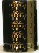
Muse KG, 10.000uF, 50V, 30x45mm will fit perfectly into boards.
I never use L1. If you think you need one, 1.5mm coper enameled wire, 10turns on 12mm diameter will suffice.
Whoops! Sorry. I was only looking at the ones available from Percy, which are the larger Type II. I see also that Nichicon has a smaller type KS series comparable to the KG Type I, but I haven't seen them anywhere.
Where do you get your parts from? Especially the Vishay C1 cap?
pooge said:Especially the Vishay C1 cap?
Would that be these: http://mouser.com/Search/ProductDetail.aspx?qs=zsqpZXbm4xw3PgUpuT0ISA==
Sheldon
pooge said:
Be cafeful with the KS caps at Mouser, in that the described sizes don't compare with the Nichicon KS spec sheet.
Note the 10000uf/50v should be 35mm dia--too large. However, the 10000uf/63v model LKS1J103MESB should fit.
Sheldon said:
Would that be these: http://mouser.com/Search/ProductDetail.aspx?qs=zsqpZXbm4xw3PgUpuT0ISA==
Sheldon
Not the same. Those are polyester film.
These oughta be close: http://mouser.com/Search/ProductDetail.aspx?qs=GyBxYo12BSucMc7iryG6Bw==
Sheldon
Sheldon
pooge said:
Be cafeful with the KS caps at Mouser, in that the described sizes don't compare with the Nichicon KS spec sheet.
Note the 10000uf/50v should be 35mm dia--too large. However, the 10000uf/63v model LKS1J103MESB should fit.
Looks like the 12000uf/50v 647-LKS1H123MESB at Mouser will fit and be cheaper than the 10000uf/50v they offer.
MKP1839
http://uk.farnell.com/vishay/mkp1839510164/capacitor-axial-mkp-1-0uf-160v/dp/1413918
MUSE KG 10000uF/50V from e-bay
http://uk.farnell.com/vishay/mkp1839510164/capacitor-axial-mkp-1-0uf-160v/dp/1413918
MUSE KG 10000uF/50V from e-bay
Attachments
roender said:RMI-FC100 amplifier BOM
C1, C10,C11: WIMA MKS4 63V
Noticed an error here. C10 and C11 have 5mm lead spacing (PCM5)
Therefore, these should be MKS2.
Original C1 had 7.5mm PCM, but changed to Vishay axial in later mod.
pooge said:
Noticed an error here. C10 and C11 have 5mm lead spacing (PCM5)
Therefore, these should be MKS2.
Original C1 had 7.5mm PCM, but changed to Vishay axial in later mod.
On the other hand, a Wima MKP2 polypropylene at 100v will also fit in C10 and C11. Could a MKP be of better use here as a match to the MKP shunting the output of the front end power supply board?
Re: Excel version
I've got a very similar BOM being developed for Noth American suppliers, but not ready to post an incomplete one.
barryblue said:Hi Mihai
Thank you for the opportunity to build your amplifier.
Please see the attached excel spreadsheet with some of the components marked with potential suppliers and hyperlinks.
I've got a very similar BOM being developed for Noth American suppliers, but not ready to post an incomplete one.
A quite reliable source to get genuine Nichicon KG 10000uF 50V
http://shop.hifidiy.net/product/262.htm
I ain't affiliated with this internet shop.
http://shop.hifidiy.net/product/262.htm
I ain't affiliated with this internet shop.
Attachments
Do they have an English view on that website?
Another alternative is to put some more readily available smaller ones on board, and make up the difference with some off board, near the bridge. Yes, it costs more, but doing so can reduce the size of charging loops, especially if a resistor or inductor is placed between sets like shown in the front end supply.
Also, as proposed by Bob Cordell, an axial electrolytic of about 500uf can be inserted from +rail to -rail across the series pair of fuse holders to provide a smaller loop.
pooge said:Do they have an English view on that website?
Another alternative is to put some more readily available smaller ones on board, and make up the difference with some off board, near the bridge. Yes, it costs more, but doing so can reduce the size of charging loops, especially if a resistor or inductor is placed between sets like shown in the front end supply.
Also, as proposed by Bob Cordell, an axial electrolytic of about 500uf can be inserted from +rail to -rail across the series pair of fuse holders to provide a smaller loop.
pooge,
In the frontend PSU we can use without problems CRC filter because the current flow is constant. We don't have the same situation in the current amplification stage.
Cheers,
M
roender said:
pooge,
In the frontend PSU we can use without problems CRC filter because the current flow is constant. We don't have the same situation in the current amplification stage.
Cheers,
M
Roender,
This was discussed extensively on another thread. The charging pulses from the rectifier are quite high and of short duration. As such, the pulses in these wires can couple to the circuitry. The idea of separating the caps is to keep the rectified charge pulses localized in a small loop area between the transformer/bridge/first cap combination. A separate bridge for each secondary winding is used, and the secondary windings are not connected together. The small resistors in the lines and ground between the first caps and the second caps help isolate the ground currents from the charging pulses from mixing with the ground currents in the amplifier, by directing the pulses into the local loop. While the resistors do provide some filtering, and there may be an adjustment to cap values, I would look at the resistors between caps as being of similar funtionality as the R25 resistor in your amp.
- Home
- Amplifiers
- Solid State
- RMI-FC100, a single stage audio power amplifier

