roender said:
Denis,
I think you have some ground wiring problem, or more than 92bB SPL speakers.
Where did you put the speaker return wire? Into the star ground, in the middle of the board?

Yes it's connected to the star ground. I suspect the small transformers i have used for the drive supply, but i'm not shure.
I have made some tests (distance it ) and i have found the front end pair very sensitive to electro-magnetic fields.
Maybe my ground plane PCB (not grounded in fact ) ????
If you have some other idea.
Thanks
MJL21193 said:Here's the first working model of my version with bjt input:
No comments on my escapades?
Oh well.I put it on a heatsink and did a full power test - looks very good. I have configured it to run on +/-72V rails, but input sensitivity limited to 150 watts output. This ensures plenty of headroom to avoid clipping.I worked out some of the bugs and finalized my layout:
An externally hosted image should be here but it was not working when we last tested it.
All of the outputs plus the CFP drivers are mounted under the board in contact with the heatsink.
Thanks roender for the great design.
housing said:Hi Mihai,
How did you match the transistors? Thanks!
Which transistors?
Any opinion on which of these transformers would be best for the output stage for a single channel? The Antek is a lot cheaper and heavier, but I read an opinion somewhere, without explanation, that the Avel was better quality. Is anyone familiar which any quality difference between these lines of transformers?
Avel Transformer
Antek Transformer
Has anyone found a USA supplier for a standard off-the-shelf transformer for the input stage?
Avel Transformer
Antek Transformer
Has anyone found a USA supplier for a standard off-the-shelf transformer for the input stage?
Mihai, just wanted to offer my congratulations on a clean, capable design that shows that you have put a lot of thought and time into it. It is a pleasure to look over your work. Nice!
In fact, it looks like something that I would design (^o^).
Happy holidays! jonathan carr
In fact, it looks like something that I would design (^o^).
Happy holidays! jonathan carr
jcarr said:Mihai, just wanted to offer my congratulations on a clean, capable design that shows that you have put a lot of thought and time into it. It is a pleasure to look over your work. Nice!
In fact, it looks like something that I would design (^o^).
Happy holidays! jonathan carr
Mr. Jonathan Carr,
Thank you very much for your kind words.
I must confess that I am a big fan of yours and I'm glad that we have you back on diyaudio ... I hope.
This design is very much yours. I was guided by many posts you had writhed on the net.
I would like to ask you a question, if I may?
I've been thinking to version two of RMI-FC100 for a while. I want to use Li Ion rechargeable battery as front end power supply and I don't know if i could replace LTP CCS with a simple resistor and also all folded cascode CCSs with JFETs configurated as CCS at zero TC, in order to allow an exceptional HF behavior.
I would like to make this design as simple as possible from singal path point of view.
What do you think about?
Best regards and
Happy Holidays,
Mihai Rauta
Mihai: Thank you for the kind words. And thanks also for the acknowledgement that you gave me at the beginning of this thread. That was wholly unexpected, and I appreciate and respect you the more for it.
I haven't so much experience with using Li Ion batteries (I've experimented with video-cam batteries) with audio gear, but my experience with other types of batteries is that there are marked differences in sound, depending not only on the technology employed but also the manufacturer and type. Experiencing this can be a dismaying surprise at first, and a decided nuisance subsequently. For one's own purposes, you can test different batteries and settle for the one that pleases your ears the most, but when it comes to specifying a build specification for other RMI-FC100 builders, I think it would be best if you specified a type of battery that is available in as many countries as possible.
To mention an alternative to batteries, you may like to try your hand at some type of "never-connected" power supply, similar to the circuit that I posted years ago, or the one that EC Designs has come up with recently for his DAC project. Based on personal experience (as well as listening feedback from dealers and customers), I can vouch that, in terms of sonic benefits, this is a worthwhile area for development effort - possibly more so than the amplifier circuit itself.
As you probably know, I normally don't like to swap resistors in for CCSs, because there is too much chance for current modulation. The exception would be if you have a lot of voltage headroom, and even then it would be a "maybe I'll think about it" situation (^o^). Voltage sag and back-EMF generated due to the fluctuating current demands of the circuit acting upon the inductances of PCB traces can be a problem in any situation, and IMO it is better to keep the circuit in a configuration that allows it to reject conceivable ill-effects as much as possible. The LTP pivot is a sensitive node which has direct consequences on the CMRR, and so at least I would not replace the CCS here for a resistor. If you are worried about the effects of Q8's capacitance, you could try inserting a series resistor.
OTOH, I certainly make use of JFET CCSs (and one-piece JFET CCSs from the likes of Siliconix and Ishizuka-SemiTec) in my own designs. For non-demanding locations, I may simply choose to use the JFET CCS as is. But for more critical locations, I prefer to shield the CCS with a bipolar or MOSFET cascode (thereby fixing the voltage and therefore the operating point). Also I will select the cascode voltage to keep the CCS in the most linear part of its curve, so that power supply variations or voltage reference modulations have as little effect on the current as possible.
To feed Q13 and Q11 with a JFET CCS will be no problem at all, since Q13 and Q11 will keep the operating voltage across the JFET CCS constant. FWIW, this alteration would be fairly close to how the 4-2SE preamp is designed.
IME, making the design simple from the signal point of view often means that it physically gets more complex rather than less. I believe in attempting to envision everything that could possibly be going on, and arrange the design (schematic and board layout) so that as many factors as possible are accounted for.
To accomplish this and yet keep the design simple and elegant is undoubtedly and always the most difficult thing to do. I'd suggest that you first get the total functionality for RMI-FC100 MkII where you want it to be (almost regardless of complexity), and then work on streamlining it over time.
So you want to develop a Mk II? That feeling sounds rather familiar (^o^).
Let me know if I can be of any help.
regards, jonathan carr
Mihai,
I got four sets of boards from the recent buy. I'll probably build later this spring. A couple of questions:
I may have missed it, but is there an image of the main board with the parts labeled that I have missed? No problem, if not, as the schematic and pictures here should do.
I will probably use one front end supply for each stereo pair of power amps. But I'd like to use the two extra for other projects. Any limitations on reducing the input voltage and reference zener for other applications?
thanks,
Sheldon
Sheldon said:Mihai,
I may have missed it, but is there an image of the main board with the parts labeled that I have missed? No problem, if not, as the schematic and pictures here should do.
thanks,
Sheldon
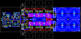
Hi Seldon,
Sorry for no PCB component label layer ... it is so difficult to do that in EAGLE.
This is all I can do for you:
Attachments
Sheldon said:
I will probably use one front end supply for each stereo pair of power amps. But I'd like to use the two extra for other projects. Any limitations on reducing the input voltage and reference zener for other applications?
It is possible to use other output voltages by putting other zener values
but don't forget that this is a shunt PSU. You have to modify CCS current in order to keep at least 10-15mA through PSU output transistors (MJL15034/35).Happy Holidays,
Mihai
roender said:
Hi Seldon,
Sorry for no PCB component label layer ... it is so difficult to do that in EAGLE.
This is all I can do for you:
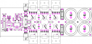
Could you drop the red. blue, purple and black colors, and just leave the green vias? That's a LOT of printer ink, and not really helpful to visualize parts layout.
pooge said:
Could you drop the red. blue, purple and black colors, and just leave the green vias? That's a LOT of printer ink, and not really helpful to visualize parts layout.
It is better now?
Attachments
- Home
- Amplifiers
- Solid State
- RMI-FC100, a single stage audio power amplifier