Re: Re: Re: Re: Re: Re: Cmcl
Nope. A much simpler setup, based on a circuit idea posted on this forum some time ago by Eva. Works very nice and requires only a dual micropower comparator. TLC352 works fine as well.
andy_c said:
Looks really nice!
For the triac control of the soft start circuitry, are you using a microcontroller or some kind of triac control chip like the TDA1085C used in the Bryston amps?
Nope. A much simpler setup, based on a circuit idea posted on this forum some time ago by Eva. Works very nice and requires only a dual micropower comparator. TLC352 works fine as well.
Attachments
Re: Almost done...
From what I can see in the photo, it looks like you've mounted the heatsinks with fins horizontally. I don't see how they would work anything close to optimal in that configuration, since convection wouldn't direct much airflow between the fins, and you're not making use of but a fraction of the surface area of the heatsinks.
syn08 said:Site to be updated soon...
From what I can see in the photo, it looks like you've mounted the heatsinks with fins horizontally. I don't see how they would work anything close to optimal in that configuration, since convection wouldn't direct much airflow between the fins, and you're not making use of but a fraction of the surface area of the heatsinks.
Re: Cmcl
Is temperature dependency the reason this type of current mirror is not commonly seen in audio? I have only really seen it in Hawksford's transimpedance amplifier before.
Thanks for the explanation.Edmond Stuart said:Also notice that this version makes use of very simple current mirrors (Q7, R9, R18, respectively Q10,R12,R20), instead of the more commonly used two transistor topology.
Is temperature dependency the reason this type of current mirror is not commonly seen in audio? I have only really seen it in Hawksford's transimpedance amplifier before.
Re: Re: Re: Re: Re: Cmcl
Neither Edmond; it is my Deutsche bockwurst.

Cheers,
Glen
Edmond Stuart said:PS: As for miss Weisz, what does she like more? You or your hot VAS?
Neither Edmond; it is my Deutsche bockwurst.
Cheers,
Glen
Re: Re: Almost done...
Agreed but sometimes you have to work with what's available. Those HSs were around $50 (including shipping from the US) a pair on EBay. I was unable to find anything with vertical fins anywhere close to that price range. Ro-Theta here in Toronto quoted me $150 a piece (that is, $300/pair plus taxes).
Another issue was with the HS positions. Ideally they should be built as the two sides of the case. Well, I was unable to find a decent priced, right sized, case with integrated HSs that would not run into $500-$700, plus shipping from Europe or Thailand, plus taxes, plus customs, plus spares readily available. I am also not ready to invest in a metal shop so what was left as an option was a 4RU Bud Industries case for $150. Top cover is perforated, of course.
The HSs are oversized and the fans control (MAX6665ASA55) is taking care of any transient thermal conditions.
abzug said:
From what I can see in the photo, it looks like you've mounted the heatsinks with fins horizontally. I don't see how they would work anything close to optimal in that configuration, since convection wouldn't direct much airflow between the fins, and you're not making use of but a fraction of the surface area of the heatsinks.
Agreed but sometimes you have to work with what's available. Those HSs were around $50 (including shipping from the US) a pair on EBay. I was unable to find anything with vertical fins anywhere close to that price range. Ro-Theta here in Toronto quoted me $150 a piece (that is, $300/pair plus taxes).
Another issue was with the HS positions. Ideally they should be built as the two sides of the case. Well, I was unable to find a decent priced, right sized, case with integrated HSs that would not run into $500-$700, plus shipping from Europe or Thailand, plus taxes, plus customs, plus spares readily available. I am also not ready to invest in a metal shop so what was left as an option was a 4RU Bud Industries case for $150. Top cover is perforated, of course.
The HSs are oversized and the fans control (MAX6665ASA55) is taking care of any transient thermal conditions.
Re: Re: Re: Re: Re: Re: Cmcl
The input impedance is rather low and the gain is 1. The target S/N for 1V RMS input is -120dB in an unweighted 20 khz bandwidth, but only measurements on the final PCB will show the exact values (measuring low noise levels on a breadboard is impossible).
Overall, the S/N ratio with the balanced input stage will be worse than the single ended input S/N. Transformers can potentially do better in terms of preserving the S/N and CMRR, but I don't really like the idea.
G.Kleinschmidt said:
Would that be a fully differential amp with shunt feedback? If so, how did you address the issue of input impedance and feedback resistor noise contribution?
The input impedance is rather low and the gain is 1. The target S/N for 1V RMS input is -120dB in an unweighted 20 khz bandwidth, but only measurements on the final PCB will show the exact values (measuring low noise levels on a breadboard is impossible).
Overall, the S/N ratio with the balanced input stage will be worse than the single ended input S/N. Transformers can potentially do better in terms of preserving the S/N and CMRR, but I don't really like the idea.
Re: Re: Re: Re: Re: Re: Re: Cmcl
What I did with my design was to make a pair of discrete opamps configured as unity gain followers / buffers for each input, to provide a high input impedance (100k). The noise contribution of the input followers can be made extremely small, and lower value feedback resistors are then allowed in the fully differential section.
Of couse, this adds a great deal more complexity, but that's all part of the fun of it, IMO.
Another question - My amp is a bridged design (two idependent, but identical power amps per channel), so I make use of both complementary outputs from the differential opamp stage.
How do you make use the differential outputs to drive the single ended input of the PGP?
One output must be used in reference to the other (you basically get OL linearity if you measure/take an output individually, referenced to ground).
Cheers,
Glen
syn08 said:
The input impedance is rather low and the gain is 1. The target S/N for 1V RMS input is -120dB in an unweighted 20 khz bandwidth, but only measurements on the final PCB will show the exact values (measuring low noise levels on a breadboard is impossible).
Overall, the S/N ratio with the balanced input stage will be worse than the single ended input S/N. Transformers can potentially do better in terms of preserving the S/N and CMRR, but I don't really like the idea.
What I did with my design was to make a pair of discrete opamps configured as unity gain followers / buffers for each input, to provide a high input impedance (100k). The noise contribution of the input followers can be made extremely small, and lower value feedback resistors are then allowed in the fully differential section.
Of couse, this adds a great deal more complexity, but that's all part of the fun of it, IMO.
Another question - My amp is a bridged design (two idependent, but identical power amps per channel), so I make use of both complementary outputs from the differential opamp stage.
How do you make use the differential outputs to drive the single ended input of the PGP?
One output must be used in reference to the other (you basically get OL linearity if you measure/take an output individually, referenced to ground).
Cheers,
Glen
Re: Re: Re: Re: Re: Re: Re: Re: Cmcl
With two input buffers, have you estimated the CMRR? Worst case (opamp dispersion, resistor dispersion) its not going to be great...
The output is single ended, that's the output stage that I added to bruno's differential circuit. Full schematic will be posted on the web site as soon as I'm done with the measurements.
G.Kleinschmidt said:
What I did with my design was to make a pair of discrete opamps configured as unity gain followers / buffers for each input, to provide a high input impedance (100k). The noise contribution of the input followers can be made extremely small, and lower value feedback resistors are then allowed in the fully differential section.
Another question - My amp is a bridged design (two idependent, but identical power amps per channel), so I make use of both complementary outputs from the differential opamp stage.
How do you make use the differential outputs to drive the single ended input of the PGP?
Cheers,
Glen
With two input buffers, have you estimated the CMRR? Worst case (opamp dispersion, resistor dispersion) its not going to be great...
The output is single ended, that's the output stage that I added to bruno's differential circuit. Full schematic will be posted on the web site as soon as I'm done with the measurements.
Re: Re: Re: Re: Re: Re: Re: Cmcl
what component values need changing to suit 220/240Vac?
C1=?
R1=?
U2=?
any others?
Hi Syn,syn08 said:
Nope. A much simpler setup, based on a circuit idea posted on this forum some time ago by Eva. Works very nice and requires only a dual micropower comparator. TLC352 works fine as well.
what component values need changing to suit 220/240Vac?
C1=?
R1=?
U2=?
any others?
Re: Re: Cmcl
Hi Bobby,
Yes, I think so. Another reason is probably that a two trannies mirror produces less distortion. BTW, this is not of any concern in a CMCL.
Cheers, Edmond.
abzug said:Thanks for the explanation.
Is temperature dependency the reason this type of current mirror is not commonly seen in audio? I have only really seen it in Hawksford's transimpedance amplifier before.
Hi Bobby,
Yes, I think so. Another reason is probably that a two trannies mirror produces less distortion. BTW, this is not of any concern in a CMCL.
Cheers, Edmond.
Re: Re: Re: Re: Re: Re: Re: Re: Re: Cmcl
The CMRR really isn't effected much - input buffer opamps work fine for professional instrumentation amplifiers, afterall. The buffer opamps have 100% nfb, so (feedback) resistor dispertion doesn't come into it. Each opamp is identical and has a unity gain frequency >4MHz, so OLG throughout the entire audio spectrum and beyond is ample. Unity gain accuracy, phase shift deviation, Z-out, etc is therefore very tight.
syn08 said:
With two input buffers, have you estimated the CMRR? Worst case (opamp dispersion, resistor dispersion) its not going to be great...
The CMRR really isn't effected much - input buffer opamps work fine for professional instrumentation amplifiers, afterall. The buffer opamps have 100% nfb, so (feedback) resistor dispertion doesn't come into it. Each opamp is identical and has a unity gain frequency >4MHz, so OLG throughout the entire audio spectrum and beyond is ample. Unity gain accuracy, phase shift deviation, Z-out, etc is therefore very tight.
Re: Re: Re: Re: Re: Re: Re: Cmcl
This is probably a dumb question. If the circuit fails to turn on the triac, what prevents the soft-start resistor from catching fire?
Cheers,
Bob
syn08 said:
Nope. A much simpler setup, based on a circuit idea posted on this forum some time ago by Eva. Works very nice and requires only a dual micropower comparator. TLC352 works fine as well.
This is probably a dumb question. If the circuit fails to turn on the triac, what prevents the soft-start resistor from catching fire?
Cheers,
Bob
Re: Re: Re: Re: Re: Re: Re: Re: Cmcl
There are no dumb questions, but only dumb answers.
My dumb answer is: nothing. But then there are no reasons why the triac would fail to fire and anyway a triac is much safer than a relay.
Bob Cordell said:
This is probably a dumb question. If the circuit fails to turn on the triac, what prevents the soft-start resistor from catching fire?
Cheers,
Bob
There are no dumb questions, but only dumb answers.
My dumb answer is: nothing. But then there are no reasons why the triac would fail to fire and anyway a triac is much safer than a relay.
Re: Re: Re: Re: Re: Re: Re: Re: Re: Cmcl
What if the triac is an a dumb mood?
syn08 said:There are no dumb questions, but only dumb answers.
My dumb answer is: nothing. But then there are no reasons why the triac would fail to fire and anyway a triac is much safer than a relay.
What if the triac is an a dumb mood?
Re: Re: Re: Re: Re: Re: Re: Cmcl
Ah yes - that was a nice thread over there in Power Supplies.
I've been looking for a solution that uses variable phase control on the triac. I wish I could figure out what's going on in the Bryston soft start circuit! I guess I'll start out with a simple circuit first and work my way up to a phase control circuit later.
syn08 said:Nope. A much simpler setup, based on a circuit idea posted on this forum some time ago by Eva. Works very nice and requires only a dual micropower comparator. TLC352 works fine as well.
Ah yes - that was a nice thread over there in Power Supplies.
I've been looking for a solution that uses variable phase control on the triac. I wish I could figure out what's going on in the Bryston soft start circuit! I guess I'll start out with a simple circuit first and work my way up to a phase control circuit later.
Re: Re: Re: Re: Re: Re: Re: Re: Cmcl
A variable phase control circuit should not be a problem if a specialized ic is used. I was looking myself for such a solution and the problem is in how to power the controller. Due to the supply current requirements I doubt a capacitive divider can be used, while a power resistor is to me not a good option.
andy_c said:
I've been looking for a solution that uses variable phase control on the triac. I wish I could figure out what's going on in the Bryston soft start circuit! I guess I'll start out with a simple circuit first and work my way up to a phase control circuit later.
A variable phase control circuit should not be a problem if a specialized ic is used. I was looking myself for such a solution and the problem is in how to power the controller. Due to the supply current requirements I doubt a capacitive divider can be used, while a power resistor is to me not a good option.
Re: Re: Re: Re: Re: Re: Re: Re: Cmcl
Andrew,
I'm on the road now, will do some calculations tonight and let you know.
AndrewT said:Hi Syn,
what component values need changing to suit 220/240Vac?
C1=?
R1=?
U2=?
any others?
Andrew,
I'm on the road now, will do some calculations tonight and let you know.
Re: Re: Re: Re: Re: Re: Re: Re: Re: Cmcl
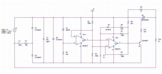
This one works ok for me.
The only snag is C5 size…
syn08 said:
Due to the supply current requirements I doubt a capacitive divider can be used, while a power resistor is to me not a good option.
This one works ok for me.
The only snag is C5 size…
Attachments
Re: phase control circuit
You mean due to DC (from asymmetrical chopping of the positive and negative half cycles)? Wouldn't this tend to go away once the 100 percent duty cycle is reached? Or is it some other cause you're referring to? It would be nice to get rid of the high-power resistor.
I did notice that the Bryston circuits have DC compensation that can buck out two diode drops (the full wave bridge with the large capacitors across it in the schematics). Are the Brystons known to have the buzzing transformer problem?
dimitri said:Andy, this is not a good idea.
Power transformer will sing.
You mean due to DC (from asymmetrical chopping of the positive and negative half cycles)? Wouldn't this tend to go away once the 100 percent duty cycle is reached? Or is it some other cause you're referring to? It would be nice to get rid of the high-power resistor.
I did notice that the Bryston circuits have DC compensation that can buck out two diode drops (the full wave bridge with the large capacitors across it in the schematics). Are the Brystons known to have the buzzing transformer problem?
- Status
- This old topic is closed. If you want to reopen this topic, contact a moderator using the "Report Post" button.
- Home
- Amplifiers
- Solid State
- PGP (Pretty Good Poweramp)