anatech said:The last one I played with turned out that around 9 dB was the best.
I don't doubt your experience, and at the same time I suspect that there may be something else going on with your system.
For example, I have found that getting rid of the feedback in the LAST component makes more difference than in the FIRST component. (In other words, a completely zero-feedback system.) If you would care to post the schematic of your design, I would be glad to make any relevant comments.
In recent years, more and more commercial firms are going the no-feedback approach. John Curl's Blowtorch is zero feedback. The power amps I designed for Theta are zero feedback. That line has been taken over by Dave Reich (original designer for Classe), and so far as I know he's had 8 years to add feedback and hasn't done so. One of the guys that started Ayre with me went to Wadia in the mid-'90s. He talked them into getting rid of the feedback in their designs. First they used a no-feedback output buffer (BUF634, I believe), and then they bought a zero-feedback current conveyor design for their current-to-voltage converter. (Nee Photonics PA630 and re-named "Swift Current", patent number 4,983,930). Each time they made the change to less feedback, the results were universally acclaimed as a significant improvement. And finally this year Krell has announced zero-feedback preamps, although I guess they still haven't figured out how to do this for their power amps (those still use "8 dB of feedback in the output stage".)
Hi Charles,
I'll have to get the paperwork together. But I can describe some of it accurately enough. The test system was a project and is a bit of a dog's breakfast.
We start with a Counterpoint SA-100 with blown outputs (no kidding!). I corrected most of the gross design errors and added a high voltage regulator for the tube voltage amp stage. The original circuit was modified to correct further problems and remove heavy non-linear feedback from the tube driver stage. A "real" feedback stage was installed (purely resistive with a blocking capacitor). So the tube voltage amp stage is still very flawed, but much better and with lower distortion. The output stage was basically a discrete BUF03 and BJT all the way. The amp became just listenable at this stage. I used current sources instead of resistors to supply operating current. The buffer used a emitter follower double and a double input stage.
The detail was very good while retaining the good part of the "Counterpoint sound". I also tried feedback that came off the input of the output buffer stage. I found I needed to enclose that in the loop as well as the output fuse to get good sound out of it. This improved the quality by a small amount. I inflicted this system on SY.
With better voltage amplifier stage I still needed feedback. This was a standard, cascoded J FET differential with current mirrors to form the VAS. Just a basic voltage amp. This was far better than the Counterpoint donor.
I guess my point is that different systems benefit from various levels of feedback taken from different points in the circuit. I am waiting for my new Cyrus Mono X amplifers to arrive. These I am looking forward too. They are based on a no feedback design, not even around different stages. They are based on Diamond buffers as well. So, no feedback in a classic sense, not even partial. I sure hope they sound good.
-Chris
anatech said:The output stage was basically a discrete BUF03 and BJT all the way. The amp became just listenable at this stage. I used current sources instead of resistors to supply operating current. The buffer used a emitter follower double and a double input stage.
I'm one of those guys that is more visually oriented. I can't have a conversation without a pen and paper to make diagrams. So I'm not sure if I'm following you completely.
But in my experience, if you are using BJT's, you HAVE to use a triple. A double will put too much loading on the front end, creating too much distortion.
MOSFET's are another story, but I don't want to go there if we don't have to. (Although I believe that the SA-100 originally had vertical MOSFET outputs.)
anatech said:I am waiting for my new Cyrus Mono X amplifers to arrive. These I am looking forward too. They are based on a no feedback design, not even around different stages. They are based on Diamond buffers as well. So, no feedback in a classic sense, not even partial. I sure hope they sound good.
I haven't heard of these, but it sounds like another company is joining the "no-feedback" camp. Please be sure to let us know how they sound.
Well, I just went to the Cyrus website. They "kind of" make no-feedback amps. Here is a quote from their website:
"The current amplifier is an error corrected bipolar emitter follower designed to drive equally well into all impedances. In the Mono X neither of these stages have any global feedback."
First of all, "error correction" is simply a feedback loop with gain in the feedback direction. The only way that you can keep this type of thing from oscillating like a radio station is to only include a very short part of the circuit (not the whole thing.)
When you see catch phrases like "no GLOBAL feedback", then my alarm bells start going off. The problem is that there are dozens of ways to apply feedback, but only two or three terms that are commonly used. So there is PLENTY of room for mischief, misinterpretation, and outright misrepresentation.
On the other hand, I am told that the Eskimos have 8 different words for "snow". I think we could learn something from them in that regard...
And while I'm being picky, Cyrus has this to say about the front end:
"The voltage gain amplifier uses a zero feedback complementary bootstrap cascoded 'class A' buffer which drives a precision resistor."
Please note that a bootstrap is a *positive* feedback circuit....
"The voltage gain amplifier uses a zero feedback complementary bootstrap cascoded 'class A' buffer which drives a precision resistor."
Please note that a bootstrap is a *positive* feedback circuit....
Hi Charles,
I'm sorry, I can't release the diagrams. Not by choice.
The input stage is a diamond buffer (modified) and has no bootstrapping. I was lucky enough to see it in design when I visited the factory in 2004 and had a good talk with the engineer who did the design. I have been working on some very similar designs and this is the only reason I ordered them sight unseen.
The next stage is a diamond buffer also. The output stage is very, very similar to what I have worked on myself and does not use feedback that I can see. The signal flow never goes backwards.
The material you read on the website is inaccurate. So much for advertising, never believe what you read!
Anyway, this amplifier is a true nothing but local(unavoidable) feedback design. There are no feedback loops encompassing any stage, not does it have feedback that excludes the output stage (Stassis flavour). So now you know much more since you are an experienced designer.
I will report on it's sound quality once I run it a bit. I am comparing it to a Marantz 300DC that I rebuilt. No ceramic caps at all now, all electrolytics replaced and bypassed. Voltage amp regulators as well. Yes, a high feedback design driving PSB Stratus Gold speakers (with aluminum dome tweeters. These will show nasty sounds easily). This is also a J FET input, modified power diamond buffer design.
-Chris
I'm sorry, I can't release the diagrams. Not by choice.
The input stage is a diamond buffer (modified) and has no bootstrapping. I was lucky enough to see it in design when I visited the factory in 2004 and had a good talk with the engineer who did the design. I have been working on some very similar designs and this is the only reason I ordered them sight unseen.
The next stage is a diamond buffer also. The output stage is very, very similar to what I have worked on myself and does not use feedback that I can see. The signal flow never goes backwards.
The material you read on the website is inaccurate. So much for advertising, never believe what you read!
Anyway, this amplifier is a true nothing but local(unavoidable) feedback design. There are no feedback loops encompassing any stage, not does it have feedback that excludes the output stage (Stassis flavour). So now you know much more since you are an experienced designer.
I will report on it's sound quality once I run it a bit. I am comparing it to a Marantz 300DC that I rebuilt. No ceramic caps at all now, all electrolytics replaced and bypassed. Voltage amp regulators as well. Yes, a high feedback design driving PSB Stratus Gold speakers (with aluminum dome tweeters. These will show nasty sounds easily). This is also a J FET input, modified power diamond buffer design.
Yes, but you can fold the transistors around. My original design had four transistors common emitter, now I've gone down to three.But in my experience, if you are using BJT's, you HAVE to use a triple. A double will put too much loading on the front end, creating too much distortion.
-Chris
anatech said:Anyway, this amplifier is a true nothing but local (unavoidable) feedback design. There are no feedback loops encompassing any stage.
Yes, this is the semantics problem I was talking about earlier. When talking about a single stage, such as an emitter follower, then the common practice is to say that it has "100% feedback".
But when talking about a complete circuit, there is no way to avoid some form of what is more properly called "degeneration", if only from the intrinsic re inside the device. (If there weren't some local degeneration inherent in the device, then it would have infinite gain!).
So there are certain people that like to argue and say that "there is no such thing as a zero-feedback amplifier". Which in a sense is true, but does nothing to illuminate the various approaches to circuit design and instead only obfuscates the true differences between various circuits.
But as someone that has to sell amps in the real world, I don't like to use the word "degeneration" in marketing material meant for mass consumption. Why? Because it sounds too much like "a degenerate". Those should be locked up in jail, not used in a music system!
anatech said:PSB Stratus Gold speakers (with aluminum dome tweeters. These will show nasty sounds easily).
The reason they will show nasty sounds easily is because of the "phase plug" that is in front of the diaphragm. This is actually a Helmholtz resonator that has been mis-named for marketing reasons. It is tuned to about 16 kHz to boost the output that would otherwise be falling off due to the path-length-difference from the perimeter of the dome to your ears and the apex of the dome.
Do yourself a huge favor. Get a small, sharp pair of dikes. Then cut off the three attachment points and get rid of the "phase plug". You will lose a few dB of output in the top half-octave, but you will also lose a ringing, resonant mess. You will be stunned at how smooth and silky a metal dome tweeter sounds when you get rid of the "phase plug".
The only down side is that you will have to listen more carefully to tell the power amps that have audible problems in the top octave.
PS -- If you like to work and are willing to relocate to Colorado, let me know. I bet we could find a job opening for you here.
Hi Charles,
I think you are right about the tweeter. I don't really care for the top end, but they sound good with an amplifier that doesn't misbehave in the top end or detail. Generally, they are not bad for the money and having a 4 ohm load I can stress a marginal design.
.
-Chris
I think you are right about the tweeter. I don't really care for the top end, but they sound good with an amplifier that doesn't misbehave in the top end or detail. Generally, they are not bad for the money and having a 4 ohm load I can stress a marginal design.
Yes. That is why I qualified my statement a little.Yes, this is the semantics problem I was talking about earlier. When talking about a single stage, such as an emitter follower, then the common practice is to say that it has "100% feedback".
.Back to preception, and I completely agree. Most people are like cattle and it doesn't take much to drive them away. I am surprised that Cyrus messed up the product info so much.I don't like to use the word "degeneration" in marketing material meant for mass consumption. Why? Because it sounds too much like "a degenerate".
That's very kind. However, with my injures I'd rather remain in Canada for the health plan. I am not expected to return to work, so I am trying to set up a lab in my basement to further my studies and relearn what I lost. Someday I'd very much like to make it down there to meet everyone.PS -- If you like to work and are willing to relocate to Colorado, let me know. I bet we could find a job opening for you here.
-Chris
anatech said:That's very kind. However, with my injures I'd rather remain in Canada for the health plan. I am not expected to return to work, so I am trying to set up a lab in my basement to further my studies and relearn what I lost.
It sounds like you may have had a traumatic brain injury (TBI). The best therapy for this is hyperbaric oxygen therapy (HBOT). Do a Google search, then read some books -- Hyperbaric Oxygen Therapy by Neubauer and The Oxygen Revolution by Harch. Then find yourself an HBOT clinic near where you live. I remember seeing an ad for one outfit in Canada that only charged $80 Canadian per session, which is about half the going rate down here.
Hi Charles,
Anyway, you've been very kind and we are very O.T. here. BTW, you have mail.
Thanks again Charles,
-Chris
Yes, plus a lot of soft tissue damage. Others have suggested this treatment and I keep forgetting to look into it. Thank you for the reminder.It sounds like you may have had a traumatic brain injury (TBI).
Anyway, you've been very kind and we are very O.T. here. BTW, you have mail.
Thanks again Charles,
-Chris
Charles Hansen said:
I'm not sure I agree with you. If this were true, all of the solid-state amps that have been built for the last 45
years would be self-destructing at an alarming rate. But in the real world, I just don't see that many amps blowing
up from this problem.
Hi Charles,
This assertion is quite wrong. You need to plug in the numbers and do the math. Many amps don't use RE smaller than
0.22 ohms, and most of those few that do use a lower RE operate the transistors at lower voltages. Moreover, many
amps built over those years have used 200-Watt TO3 devices that can achieve a lower thermal resistance from case to heat sink than TO-247 devices.
Take the Leach amp you cut your teeth on. IIRC, it used 0.33 RE with 85V rails and 200W TO3 devices. They probably
had a thermal resistance from junction to heat sink of about 0.8 C/W. Net gm was about 1.5 S at optimal Class-AB
bias with RE = 0.33.
Beta = 85V * 0.0022V/C *1.5S * 0.8C/W = 0.22
This is a very comfortable value.
A 100W amplifier with 50V rails and using quite small 0.1 ohm resistors with T0-3 output devices biased at 150 mA
and having a net gm of 3 S would have a Beta of:
Beta = 50V * 0.0022V/C * 3S * 0.8C/W = 0.26
This is also a comfortable value.
Cheers,
Bob
Re: Re: Thermal Bias Instability
Hi Pooge,
Unfortunately, this does not address the particular problem of local thermal bias stability for a given device. Its not that this is a bad idea, because it certainly does improve matters by taking the average and splitting the difference. However, taken from the perspective of just one device, in this kind of arrangement its ThermalTak diode has only 1/8 influence, which means it is only able to provide a little bit of the needed local thermal compensation for the single device under consideration.
Cheers,
Bob
pooge said:
Why not put all 16 Thermal Trak diodes in series, take the voltage across all of them and divide it down to derive a sensor voltage. Or, have two diode strings, one for each sex output, divide, and apply each one to half of a complimentary Vbe.
This way, all outputs are monitored to derive an average. The diode string could be fed from a 25ma constant current source. Also, the voltage division could be varied for less than full diode increments.
Hi Pooge,
Unfortunately, this does not address the particular problem of local thermal bias stability for a given device. Its not that this is a bad idea, because it certainly does improve matters by taking the average and splitting the difference. However, taken from the perspective of just one device, in this kind of arrangement its ThermalTak diode has only 1/8 influence, which means it is only able to provide a little bit of the needed local thermal compensation for the single device under consideration.
Cheers,
Bob
Re: Re: Re: Thermal Bias Instability
I'm not taking the perspective of just one device. I'm taking the perspective of the whole stage.
In that case, it would seem to me that 1/8 influence is better than NO influence if only a few of the diodes are used, the hottest one being one of the diodes not used.
It seems a waste not to use all of the diodes somehow. If not taking advantage of all of them, you may as well just use a sensor piggybacked on the top of one or a few output devices.
Bob Cordell said:
Hi Pooge,
Unfortunately, this does not address the particular problem of local thermal bias stability for a given device. Its not that this is a bad idea, because it certainly does improve matters by taking the average and splitting the difference. However, taken from the perspective of just one device, in this kind of arrangement its ThermalTak diode has only 1/8 influence, which means it is only able to provide a little bit of the needed local thermal compensation for the single device under consideration.
Cheers,
Bob
I'm not taking the perspective of just one device. I'm taking the perspective of the whole stage.
In that case, it would seem to me that 1/8 influence is better than NO influence if only a few of the diodes are used, the hottest one being one of the diodes not used.
It seems a waste not to use all of the diodes somehow. If not taking advantage of all of them, you may as well just use a sensor piggybacked on the top of one or a few output devices.
Hi, Mr. Hansen,
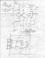
This is a non-feedback amp (at least it is what in the brochure said), but it has servo (TL071) around VBE multiplier to maintain 0Vdc offset. The output stage is biased about 20mV accross the 0.1R/5W resistors. The outputs are 2SC5200/2SA1943, 5pairs.
What is improve-able from this design?
This is a non-feedback amp (at least it is what in the brochure said
), but it has servo (TL071) around VBE multiplier to maintain 0Vdc offset. The output stage is biased about 20mV accross the 0.1R/5W resistors. The outputs are 2SC5200/2SA1943, 5pairs. What is improve-able from this design?
Attachments
Re: Re: Re: Thermal Bias Instability
If two diode strings were made, one for each sexed output group, for a complementary Vbe multipler, then the influence of each diode could be doubled.
Bob Cordell said:
Hi Pooge,
Unfortunately, this does not address the particular problem of local thermal bias stability for a given device. Its not that this is a bad idea, because it certainly does improve matters by taking the average and splitting the difference. However, taken from the perspective of just one device, in this kind of arrangement its ThermalTak diode has only 1/8 influence, which means it is only able to provide a little bit of the needed local thermal compensation for the single device under consideration.
Cheers,
Bob
If two diode strings were made, one for each sexed output group, for a complementary Vbe multipler, then the influence of each diode could be doubled.
Charles Hansen said:
But your equation doesn't give a gain of 1. When the Beta you defined is 1, then the gain is actually 2. The formula says that when the temperature goes up 1 degree (for whatever reason) that the temperature coefficient is such that you will see the temperature rise ANOTHER degree. That is a gain of 2, not 1.
When your formula gives a Beta of ZERO, then the gain is 1 (at least to my way of thinking).
Hi Charles,
This is just a matter of basic feedback theory.
In a simple feedback system, closed loop gain is given by:
G = A/(1-A*B),
Where A is the forward gain and B (Beta) is the feedback factor. The product A*B is the loop gain. For negative feedback, A*B is negative, so the denominator grows with increased amounts of NFB. When A*B is positive, we have positive feedback wherein A*B subtracts from the unity term and decreases the denominator with increased loop gain. This in turn increases G. When A*B goes to +1, the denominator goes to zero and G goes to infinity, and we have runaway or latchup.
In the case I described with my formula for local thermal stability, I used A=1 for convenience and lumped all of the loop gain into Beta. When my value of Beta goes to unity, the denominator goes to zero and we have infinite gain and runaway. When Beta = 0.5, you can see that the denominator goes to half its value when there is no feedback, meaning that G goes to twice its no-feedback value.
If you prefer, for the thermal feedback analysis, you can say that the input to the system is the base voltage and the output of the system is the bias current. The forward gain, A, is then the change in bias current for a given change in base voltage. This is simply the net transonductance of the combination of the output transistor and its emitter resistor. This is gm in my formula.
The value of Beta, looking at it this way, then becomes equal to Vce * Theta_cs * TCvbe. Vce gets us from change in current to change in power. Theta_cs gets us from change in power to change in temperature. TCvbe gets us from change in temperature to change in voltage, completing the ‘loop”.
G = gm/(1-gm * Vce * Theta_cs * TCvbe) [amperes per volt]
You can see that loop gain, which is what counts in determining how much positive feedback you have, is still the same as what it was in my formula.
I hope this makes the origin and validity of my formula more clear.
Cheers,
Bob
janneman said:Hi Edmond,
[snip]
Moderators: please can you split these posts to Bob's EC thread?
Jan Didden
Hi Jan, see for a reply the EC thread.
Cheers,
Re: Re: Thermal Bias Instability
Hi Charles,
As you said to another poster:
Like Rafiki told Simba in The Lion King, "look harder!"
You are not hearing what I am saying. Moreover, you are not plugging in the numbers and doing the math. If you do, you will see that most amplifiers, including those using paralleled devices, come out with a Beta value that is safe.
If you tell me the numbers for your ThermalTrak amp, I'll plug the numbers in for you. What RE are you using, what is your rail voltage, and how many output pairs do you have in parallel on each side? I'm guessing you are in safe territory, as your rail voltages are fairly small, if I recell from something you mentioned in an earlier post.
Cheers,
Bob
Charles Hansen said:
Again, I have not found this to be a problem in the real world. There are hundreds of thousands (if not millions!) of BJT amplifiers in the world that have paralleled output devices, but by-and-large they are pretty darned reliable. All of these theoretical considerations simply are not borne out in the real world.
Hi Charles,
As you said to another poster:
Like Rafiki told Simba in The Lion King, "look harder!"
You are not hearing what I am saying. Moreover, you are not plugging in the numbers and doing the math. If you do, you will see that most amplifiers, including those using paralleled devices, come out with a Beta value that is safe.
If you tell me the numbers for your ThermalTrak amp, I'll plug the numbers in for you. What RE are you using, what is your rail voltage, and how many output pairs do you have in parallel on each side? I'm guessing you are in safe territory, as your rail voltages are fairly small, if I recell from something you mentioned in an earlier post.
Cheers,
Bob
Bob Cordell said:In a simple feedback system, closed loop gain is given by:
G = A/(1-A*B),
Where A is the forward gain and B (Beta) is the feedback factor.
In the case I described with my formula for local thermal stability, I used A=1 for convenience and lumped all of the loop gain into Beta.
Wait just minute. I don't like any of this.
"I used A=1 for convenience." Why? What is your justification?
The way I see it, your formula you gave previously is A NOT B. That formula shows the gain in the *forward* direction, not the reverse direction. The gain in the negative direction (B or Beta) is given by the thermal compensation network.
Given your starting point, everything makes sense. But I think your starting point is incorrect.
As I said before, just look at it from an intuitive standpoint and forget the math for now. Let's say that today is hotter than yesterday and the ambient temperature goes up one degree. If the forward gain of the system (A) is 1, then the temperature of the device goes up (surprise!) one degree. I think it would be hard to argue that the forward gain of such a system is NOT 1.
But your equation said that if the ambient temperature went up one degree that the positive (forward) gain due to the tempco of the system created ANOTHER degree of temperature increase for a total of two degrees. This is clearly a forward gain of 2, and NOT a reverse gain of 1.
I don't even see how you could talk about the reverse gain (B) without including the feedback mechanism of the bias sensor.
Of course, if you want to talk about the system WITHOUT the bias sensor, just looking at the mechanisms intrinsic to the output devices themselves (such as channel resistance tempco, Vgs threshold tempco), then you could use your formula. In that case, the Vgs threshold tempco would be in the A side of things and the channel resistance tempco would be in the B side of things.
But then unless you are using lateral devices you will see that the system will ALWAYS "latch up". Which is why thermal feedback is required in the form of the bias sensor. But you have completely ignored this in your equations, and I think without adequate justification.
- Home
- Amplifiers
- Solid State
- Bob Cordell Interview: BJT vs. MOSFET