I don't understand what's so appealing with perfect bias stability.
I feel very comfotable with overbias (~160mA/device) at switch-on going to optimum at normal working conditions at moderate listening levels and finaly to underbiasing (60mA/dev or even lower) when the heatsink has a fever (~45deg.C).
I mean with proper design it should not make a big difference wheater bias current is slightly away from optimum point and negative thermal coefficient makes sense as thermal economics is concerned.
I use bjt triples( |<,|<,|<, ), complementary Vbe multiplier and pre-drivers out of main heatsink.
Adam
Re: Re: Re: Re: A question on Lateral's mosfets
Hi Charles,
The zeners I used are In5245 15V zeners, with a capacitance of 25 pF. See the Vishay datasheet. There are two in series, back-to-back, so the net is more like 13 pF.
But, more importantly, they are NOT connected to ground. The pair is connected from gate to source, so their effect is bootstrapped, just like the 1000+ pF of gate capacitance that they are connected in parallel with.
They are insignificant.
Cheers,
Bob
Charles Hansen said:
Edit: I looked at Bob's circuit. Don't forget those nice Zener diodes he has protecting the gates. Take a look at Figure 7 of the following 500 mW Zener diode data sheet:
http://www.onsemi.com/pub/Collateral/MMSZ2V4T1-D.PDF
Depending on the bias voltage, those diodes are adding another 50 or 100 pF of capacitance to ground, in addition to the explicit caps he has drawn in the circuit.
Hi Charles,
The zeners I used are In5245 15V zeners, with a capacitance of 25 pF. See the Vishay datasheet. There are two in series, back-to-back, so the net is more like 13 pF.
But, more importantly, they are NOT connected to ground. The pair is connected from gate to source, so their effect is bootstrapped, just like the 1000+ pF of gate capacitance that they are connected in parallel with.
They are insignificant.
Cheers,
Bob
With all this discussion about MOSFET gate resistors, I thought I'd mention a Renesas app note that deals with the subject here. There's a section titled "Analysis of Oscillation in Source Follower Circuits". It looks like they are neglecting Cgd though, so the results may only be pertinent to laterals.
Re: Thermal Bias Instability
Why not put all 16 Thermal Trak diodes in series, take the voltage across all of them and divide it down to derive a sensor voltage. Or, have two diode strings, one for each sex output, divide, and apply each one to half of a complimentary Vbe.
This way, all outputs are monitored to derive an average. The diode string could be fed from a 25ma constant current source. Also, the voltage division could be varied for less than full diode increments.
Bob Cordell said:Hi Charles,
The situation isn't always quite that rosy. Depending on the particular ThermalTrak bias scheme used, not all of the ThermalTrak transistors' diodes will play a full role in the Vbe multiplier. For example, let's say you build a big single-ended amplifier with eight ThermalTrak output pairs, 90V rails, and bias each transistor at 150 mA with 0.1 ohm resistors. How are you going to use all of those 16 ThermalTrak diodes, much less in a way such that each diode individually tends to the bias of its associated BJT?
Cheers,
Bob
Why not put all 16 Thermal Trak diodes in series, take the voltage across all of them and divide it down to derive a sensor voltage. Or, have two diode strings, one for each sex output, divide, and apply each one to half of a complimentary Vbe.
This way, all outputs are monitored to derive an average. The diode string could be fed from a 25ma constant current source. Also, the voltage division could be varied for less than full diode increments.
Re: Re: Re: Re: Re: A question on Lateral's mosfets
My bad. You are right.
Bob Cordell said:But, more importantly, they are NOT connected to ground. The pair is connected from gate to source, so their effect is bootstrapped, just like the 1000+ pF of gate capacitance that they are connected in parallel with.
They are insignificant.
My bad. You are right.
Re: Re: Re: Re: Re: A question on Lateral's mosfets
Yes, you are right. But only at idle.
When the parts are driven near clipping (and Vds heads towards zero), the Cgs of the vertical parts becomes much, much worse than the equivalent lateral parts. Look at Figure 12 of the app note Andy_C linked:
http://documentation.renesas.com/eng/products/transistor/rej27g0017_charalterstics.pdf
To see how this affects things (in a common-source circuit, I believe) when used for switching, compare Figure 11 (lateral) and Figure 14 (vertical). Look at those nice glitches in both the drive voltage and the output voltage caused by those non-linearities. Nasty, nasty, nasty.
Yes, this is also true, but not a huge effect. The best place to see this is Figure 1 of the Stereophile test report of our V-1 power amp:
http://stereophile.com/solidpoweramps/635/index5.html
Although not labeled on the graph, there are curves for both 8 ohm loads and 4 ohm loads. The high frequency response isn't as good into 4 ohms precisely because of the effect you mention. (The Cgs isn't fully "bootstrapped" out of the picture as the load impedance decreases.)
The way around the lower transconductance of the lateral parts is to simply use more of them. Depending on what vertical parts you are replacing, you will probably have to use 4 to 8 times as many lateral parts to get equivalent transconductance. The advantage of the lateral parts are:
a) Designed for audio, complements are easy to find.
b) Lower Cgd.
c) MUCH more linear Cgd -- lower distortion.
d) Easy to bias to zero tempco, no thermal compensation required.
e) Sounds better (try it and see!)
Disadvantages:
a) Higher cost.
Nelson Pass said:Looking at apples to apples for complementary parts, I get
between 2 and 3 times the Cdg.
Yes, you are right. But only at idle.
When the parts are driven near clipping (and Vds heads towards zero), the Cgs of the vertical parts becomes much, much worse than the equivalent lateral parts. Look at Figure 12 of the app note Andy_C linked:
http://documentation.renesas.com/eng/products/transistor/rej27g0017_charalterstics.pdf
To see how this affects things (in a common-source circuit, I believe) when used for switching, compare Figure 11 (lateral) and Figure 14 (vertical). Look at those nice glitches in both the drive voltage and the output voltage caused by those non-linearities. Nasty, nasty, nasty.
Nelson Pass said:And you have not mentioned
the higher Cgs of the laterals, which coupled with the lower
transconductance becomes another source of bandwidth loss.
Yes, this is also true, but not a huge effect. The best place to see this is Figure 1 of the Stereophile test report of our V-1 power amp:
http://stereophile.com/solidpoweramps/635/index5.html
Although not labeled on the graph, there are curves for both 8 ohm loads and 4 ohm loads. The high frequency response isn't as good into 4 ohms precisely because of the effect you mention. (The Cgs isn't fully "bootstrapped" out of the picture as the load impedance decreases.)
Nelson Pass said:I have no issue with the performance of Laterals, and $3 is
certainly not too much money for the parts, but I feel that the
Verticals offer better performance through the bass and midrange
due to the much higher transconductance. I have never found
thermal tracking or reliability to be an issue, but as you know,
I like to use lots of parts and big sinks, and I bias very high.
The way around the lower transconductance of the lateral parts is to simply use more of them. Depending on what vertical parts you are replacing, you will probably have to use 4 to 8 times as many lateral parts to get equivalent transconductance. The advantage of the lateral parts are:
a) Designed for audio, complements are easy to find.
b) Lower Cgd.
c) MUCH more linear Cgd -- lower distortion.
d) Easy to bias to zero tempco, no thermal compensation required.
e) Sounds better (try it and see!)
Disadvantages:
a) Higher cost.
Re: Thermal Bias Instability
Again, I have not found this to be a problem in the real world. There are hundreds of thousands (if not millions!) of BJT amplifiers in the world that have paralleled output devices, but by-and-large they are pretty darned reliable. All of these theoretical considerations simply are not borne out in the real world.
Bob Cordell said:In typical output stages, all of the NPN transistors will get the same base voltage via the drivers from the bias spreader. This means that, even with ThermalTrak transistors, current hogging among the eight output NPN's (for example) will still be governed by the equation I showed.
Again, I have not found this to be a problem in the real world. There are hundreds of thousands (if not millions!) of BJT amplifiers in the world that have paralleled output devices, but by-and-large they are pretty darned reliable. All of these theoretical considerations simply are not borne out in the real world.
Charles Hansen said:
"the Locanthi three-stage cascaded complementary symmetry emitter-follower output circuit, hereafter referred to as the T-circuit. (Because of its PNP-NPN symmetry, the configuration has a general appearance of a bridged-T circuit.)"
Locanthi was a true genius, making many contributions to audio, both in the field of electronics and loudspeakers. In addition to the T-circuit (which is still the best output stage extant, IMO) ...
What do you think about this output stage? It has the same input impedance as T circuit but it is more rail efficient because it has only two series BE jonctions and as a plus it is more stable as a result of local feedback on CFP driver.
Attachments
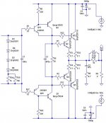
roender said:What do you think about this output stage? It has the same input impedance as T circuit but it is more rail efficient because it has only two series BE jonctions and as a plus it is more stable as a result of local feedback on CFP driver.
I personally don't like the sound that feedback creates. YMMV.
john curl said:Quibble
"To evade the truth or importance of an issue by raising trivial distinctions and objections"
What I have done? My questions are not trivial and more then that I don't think that this forum is only for "audio monsters"

roender said:It is local feedback, not global.
I don't think that it's possible to create an amp without feedback...
You asked me what I thought. I told you, and now you want to argue with me.
My opinions are based on decades of building and listening experience. Since you don't want to listen to me, I would suggest building your circuit and listening to it. If you are happy with the way it sounds, then you are all set. Nothing else matters.
If you are unhappy with the way it sounds, then you have a big job. Everything, every single detail, both in circuit topology and parts quality, will affect the way the amplifier sounds. Then you have a job to figure out what is causing the problems you are experiencing.
Good luck.
Shall I presume that you have build it an listened to it? Then, I want to thank you for your advice.
I have build it and listened and I'm very happy with results, either sonically and stability, but your presumptions based on experience make me very curios to transform my output stage into T and listen to it and compare with original.
Again, thank you very much and I'm sorry for "incident"
I have build it and listened and I'm very happy with results, either sonically and stability, but your presumptions based on experience make me very curios to transform my output stage into T and listen to it and compare with original.
Again, thank you very much and I'm sorry for "incident"
Hi Charles,
-Chris
After spending many years digging into amplifier entrails, I'd have to agree with you. Only bad designs tend to fail. The others are isolated component failure and operator error.Again, I have not found this to be a problem in the real world. There are hundreds of thousands (if not millions!) of BJT amplifiers in the world that have paralleled output devices, but by-and-large they are pretty darned reliable.
-Chris
roender said:Shall I presume that you have build it an listened to it? Then, I want to thank you for your advice.
I have build it and listened and I'm very happy with results, either sonically and stability, but your presumptions based on experience make me very curios to transform my output stage into T and listen to it and compare with original.
I haven't built that specific output stage, but I have listened to many amplifiers that use complementary feedback pairs. Even if that is the only feedback loop in the amplifier, I still hear a sonic signature due to the feedback. After listening to many amplifiers with varying designs and various ways of applying feedback, I came to the conclusion that the less feedback was employed in a design (and the shorter the loop), the more "natural" the sound quality became.
I simply took this observation to its natural conclusion -- eliminate all feedback. There have only been a handful of solid-state amplifiers made like this, and none were available at the time so I made my own. I have been using zero-feedback designs for 15 years now, and there has been nothing that makes me the slightest bit interested in using feedback in my designs.
For a nice example of a zero-feedback solid-state amplifier, please refer to this post:
http://www.diyaudio.com/forums/showthread.php?s=&postid=340375&highlight=#post340375
And if you remove some (or better yet, all) of the feedback from your amp, please let us know what you hear.
Oddly enough (since this is a DIY community) very few people have actually tried this. But the ones who have seem to also prefer the sound without feedback. Here is a link to the ONLY person I could find that actually tried it:
http://www.diyaudio.com/forums/showthread.php?postid=348739#post348739
Hi Charles,
I have tried varying the amount of feedback in some designs. My findings are that the sound quality improves to a point, then starts to become "compressed" or lifeless as feedback becomes too high. The amount of feedback depends on the design. The last one I played with turned out that around 9 dB was the best.
-Chris
Charles Hansen said:Oddly enough (since this is a DIY community) very few people have actually tried this. But the ones who have seem to also prefer the sound without feedback. Here is a link to the ONLY person I could find that actually tried it:
http://www.diyaudio.com/forums/showthread.php?postid=348739#post348739
Indeed, the experiment of removing the follower output stage
from the loop is very instructive and illuminating, however it has
been done many times, if only by a few.
At PL, the X series has had a history of releases of similar
topologies rendered in different sizes and biases, and for each
of them one of the last decisions has been to include the output
stage in the feedback loop or not.
This is an easier decision for me than for some - besides being
fearless, I use lots of outputs, high (or very high) bias, and big
(or very big) heat sinks. As a consequence, the measured specs
between including the output stage in the loop or not does not
make a huge difference, that is to say the amp's numbers are still
marketable.
For each piece, we evaluate the subjective performance with
and without feedback and make a decision. Some amplifiers were
released without output stage feedback, and others were.
It really came down to what our small listening group preferred,
and if the call was very close, we opted for no feedback.
The trend over the past year or so has been toward feedback,
at very modest levels.
This is, however, the entertainment industry, and as such is also
a fashion industry.
Hi Nelson,
Although, to some this is life and death.
-Chris
How true.This is, however, the entertainment industry, and as such is also
Although, to some this is life and death.
-Chris
- Home
- Amplifiers
- Solid State
- Bob Cordell Interview: BJT vs. MOSFET