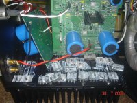
lumanauw said:This is a non-feedback amp (at least it is what in the brochure said), but it has servo (TL071) around VBE multiplier to maintain 0Vdc offset. The output stage is biased about 20mV accross the 0.1R/5W resistors. The outputs are 2SC5200/2SA1943, 5pairs.
What is improve-able from this design?
Not a bad starting point. You will have to build it and play around with it. I think you will find three potential problems:
a) I don't think the servo will work very well. But properly done, it won't even need a servo.
b) The PSRR won't be very good, so you will need excellent power supplies.
c) The output stage will tend to oscillate with capacitive loads. This is just a fact of life with BJT emitter followers. You have to take preventative measures to keep them from doing so.
Have fun, and let us know how it sounds.
Charles Hansen said:
Wait just minute. I don't like any of this.
"I used A=1 for convenience." Why? What is your justification?
The way I see it, your formula you gave previously is A NOT B. That formula shows the gain in the *forward* direction, not the reverse direction. The gain in the negative direction (B or Beta) is given by the thermal compensation network.
Given your starting point, everything makes sense. But I think your starting point is incorrect.
As I said before, just look at it from an intuitive standpoint and forget the math for now. Let's say that today is hotter than yesterday and the ambient temperature goes up one degree. If the forward gain of the system (A) is 1, then the temperature of the device goes up (surprise!) one degree. I think it would be hard to argue that the forward gain of such a system is NOT 1.
But your equation said that if the ambient temperature went up one degree that the positive (forward) gain due to the tempco of the system created ANOTHER degree of temperature increase for a total of two degrees. This is clearly a forward gain of 2, and NOT a reverse gain of 1.
I don't even see how you could talk about the reverse gain (B) without including the feedback mechanism of the bias sensor.
Of course, if you want to talk about the system WITHOUT the bias sensor, just looking at the mechanisms intrinsic to the output devices themselves (such as channel resistance tempco, Vgs threshold tempco), then you could use your formula. In that case, the Vgs threshold tempco would be in the A side of things and the channel resistance tempco would be in the B side of things.
But then unless you are using lateral devices you will see that the system will ALWAYS "latch up". Which is why thermal feedback is required in the form of the bias sensor. But you have completely ignored this in your equations, and I think without adequate justification.
Hi Charles,
Either I am doing a terrible job of explaining this, or you do not have a good understanding of how negative (or positive) feedback works. I hope it is the former
.I explained over and over again why the conventional thermal bias sensor is not being considered in this formula. I am not saying that they are unnecessary, they are just not relevant to this local short-term thermal analysis because the heat sink temperature will not change significantly in the spean of a couple of seconds.
I also patiently showed in my last post how the formula works out if you assume something other than unity for A. Did you not see that? Besides, anyone skilled in feedback theory would be completely comfortable with the concept of looking at A * Beta when stability is at issue, regardless of which part is in A and which part is in Beta.
I'll just assume that you are just skimming these posts and not reading them in sufficient detail. Please re-read it and see what you think.
Cheers,
Bob
darkfenriz said:I don't understand what's so appealing with perfect bias stability.
I feel very comfotable with overbias (~160mA/device) at switch-on going to optimum at normal working conditions at moderate listening levels and finaly to underbiasing (60mA/dev or even lower) when the heatsink has a fever (~45deg.C).
I mean with proper design it should not make a big difference wheater bias current is slightly away from optimum point and negative thermal coefficient makes sense as thermal economics is concerned.
I use bjt triples( |<,|<,|<, ), complementary Vbe multiplier and pre-drivers out of main heatsink.
Adam
Hi Adam,
I believe that there are several things important about bias stability.
First, we don't want to ever get into any form of thermal runaway. The conservative overcompensated approach you have mentioned here pretty much takes care of that.
Second, we never want to approach or go into a Class-B under-bias situation, where really bad distortion products are created (the extreme example is when we have a deadzone in the transfer function of the output stage).
Third, we want to be cautious about going into an over-bias situation, even apart from thermal runaway, to avoid the gm doubling concern that Self has mentioned. Self claims that this distortion can be just as bad as underbias, but I'm guessing it is a bit more benign.
Fourth, in general, whenever we have an important parameter in an amplifier (like output stage bias) varying with time (perhaps in step to power dissipation caused by the program material), we are potentially going to get aberrations in the performance of the amplifier that may not be measurable with conventional lab testing, but which may affect the sonic quality. With respect to undesired dynamic bias variations in the output stage, some might put this in the category of so-called memory distortion.
Cheers,
Bob
Hi, Mr. Hansen,
How can I overcome this? Now I have 2 idea in mind, putting base stoppers or put output inductor. But what is most effective?
This amp has a bad habit. This is the 3rd time it blows the whole output transistor. I wonder if this relates with the point (c) you mentioned above.
Where the PS intrusion comes from? Is it from 1N4148 cascodes?b) The PSRR won't be very good, so you will need excellent power supplies.
c) The output stage will tend to oscillate with capacitive loads. This is just a fact of life with BJT emitter followers. You have to take preventative measures to keep them from doing so.
How can I overcome this? Now I have 2 idea in mind, putting base stoppers or put output inductor. But what is most effective?
This amp has a bad habit. This is the 3rd time it blows the whole output transistor. I wonder if this relates with the point (c) you mentioned above.
Attachments
Bob Cordell said:I believe that there are several things important about bias stability.
I agree with Bob in his reply, point-by-point. The ThermalTrak parts give us a much better way to keep the bias stable as the operating conditions vary.
lumanauw said:Where the PS intrusion comes from? Is it from 1N4148 cascodes?
The best way to approach the problem is to pretend that the power supply rail is the input port to that stage. Then figure out the gain of that stage, as referenced to that input port. Some topologies are better than others in this regard.
lumanauw said:How can I overcome this? Now I have 2 idea in mind, putting base stoppers or put output inductor. But what is most effective?
99% of all power amps use an output inductor. I'm opposed to this on philosophical grounds. All of the textbooks that talk about this problem say that the answer is to use a base stopper. But in the real world the base stopper would have to be so large that it would significantly impact the output impedance of your amp.
It only took me two months to figure out an answer. Maybe you can figure out a different one sooner.
Have fun.
Bob Cordell said:Either I am doing a terrible job of explaining this, or you do not have a good understanding of how negative (or positive) feedback works. I hope it is the former
I explained over and over again why the conventional thermal bias sensor is not being considered in this formula. I am not saying that they are unnecessary, they are just not relevant to this local short-term thermal analysis because the heat sink temperature will not change significantly in the span of a couple of seconds.
I also patiently showed in my last post how the formula works out if you assume something other than unity for A. Did you not see that? Besides, anyone skilled in feedback theory would be completely comfortable with the concept of looking at A * Beta when stability is at issue, regardless of which part is in A and which part is in Beta.
I'll just assume that you are just skimming these posts and not reading them in sufficient detail. Please re-read it and see what you think.
Oh, I'm just probably being dense. Plus I am in extreme chronic pain and have a very difficult time concentrating. This is not helped much by the pain meds that I am taking (not the pain nor the concentration). But since I'm also stubborn, I'm going to continue arguing with you.
First of all, my background is physics and not electrical engineering. All of my circuit knowledge is self-taught. So I never studied "feedback theory", as I don't use feedback in any of my designs. (Actually, that's not quite true, as I do use thermal feedback in my BJT and vertical designs. And even the lateral design required some thermal feedback, but not from the output stage, which was biased at the zero tempco. Instead the INPUT stage had a positive tempco that changed the bias voltage to the output stage.)
And I still say that you are off base here.
The Beta factor that you defined before:
Beta = Theta_JS * Vce * TCvce * gm
was taken from the general formula for a feedback system:
G = A/(1-A*B)
But before we can even apply the general formula, you take the feedback out of the system saying that we want to look at the behavior of the system in that early point of time before the feedback has time to react.
(Which by the way, is clearly a shortcoming of this formula, as it only shows the steady-state response. We could get sidetracked with how this shortcoming also applies to the use of feedback in an audio amplifier, but that would be besides the point.)
Now it seems odd to me to take the formula for a feedback system but take the feedback out of the system, but there you have it. So now you have taken B (Beta) out of context and made an arbitrary definition for it. The problem is that if Beta has ANY positive value, it will lead to "latch-up". The way you have defined Beta, a positive value will lead to a higher temperature which will lead to increased dissipation, which will lead to a higher temperature, et cetera.
Now we don't need any math to tell us about a "critical" value the way that you have defined Beta. A positive value will ALWAYS lead to "latch up" It's just a question of when. Just by inspection one can see that a higher value of Beta will run away more quickly. In other words, if the ambient temperature goes up 1 degree and Beta is such that it leads to a temperature increase of 100 degrees, then it won't take much time for the output stage to self destruct. But if the ambient temperature goes up 1 degree and Beta is such that the transistor temperature heats up 1.001 degrees, then it would take quite a while before the semiconductor was in danger of thermal destruction.
Now, if you had said something like, "I have examined dozens [or better yet hundreds] of amplifiers and have empirically found that when the Beta exceeds such-and-such a value that the output devices can get into thermal runaway before the bias sensor has time to react", then I would gladly accept that. Then we could have a nice discussion about how the much shorter time constant in the feedback loop afforded by the ThermalTrak devices allowed a designer to use a higher value of the Beta that you defined without getting into trouble.
But instead you are inventing an equation that has no relationship to the actual amplifier and asserting that the critical value is 1. This simply does not hold water. It doesn't matter if the value is 0.001 or 1000, if the Beta you defined has a positive tempco it will "latch up".
On the other hand, if the Beta you defined has a value of 0, then when the ambient temperature goes up 1 degree, the temperature of the semiconductor will also rise by 1 degree.
And if the Beta you defined has a negative value, then as the ambient temperature goes up, the temperature of the semiconductor would rise by LESS than the amount of the ambient temperature increase.
So from where I'm looking, I still say that the critical value of Beta (the way you have defined it) is 0. Positive values will be unstable UNLESS they are corrected by a feedback system, while negative values will be stable without a feedback system. And clearly the higher the positive value, the easier it will be to run into trouble. So I accept your general premise that a higher positive value will tend to be of more concern than a smaller positive value. But I disagree that there is anything magic about a positive value of 1.000.
Re: Re: Re: Re: A question on Lateral's mosfets
Kevin, if you're still reading this thread I wanted to amplify my previous comments.
Yes, you are right that the interelectrode capacitances of semiconductors make pretty ****-poor capacitors. So on paper, one would think that a nice polypropylene capacitor would be much better than that.
But I actually tried that idea many years ago. The non-linear input capacitance of a vertical MOSFET can lead to very high distortion at high power levels and high frequencies. So I thought to myself, "Why not swamp the non-linear capacitance with a nice, linear external capacitor.?"
So I stuck a Wima polypropylene on the gates of the output devices, I think it was 1000 pF or so, and I made a corresponding reduction in the driving impedance of the gain stage to keep the bandwidth constant. It was enough to reduce the non-linearity by a factor of 10 or more. And the amp measured better. But guess what? It didn't sound better, it sounded worse. Not a lot worse, but noticeably worse. Basically, it still had the coloration from the non-linear capacitance of the MOSFET, but now it also had the coloration of the Wima polypropylene cap on top of that.
Another example of a clever idea that is too clever for its own good.
As far as ferrite beads go, I learned the hard way. We used them in our products for a couple of years before I realized that they have inherent problems that make for bad sound. I simply don't recommend their use for audio. I won't even use them for digital audio. Again, use the search function to look for posts under my name with the word "ferrite" and you will see my experiences.
Fanuc said:I disagree about the best cap being no cap - some are better/more linear than the caps in semiconductors! same with your dismissal with ferrite beads!
Kevin, if you're still reading this thread I wanted to amplify my previous comments.
Yes, you are right that the interelectrode capacitances of semiconductors make pretty ****-poor capacitors. So on paper, one would think that a nice polypropylene capacitor would be much better than that.
But I actually tried that idea many years ago. The non-linear input capacitance of a vertical MOSFET can lead to very high distortion at high power levels and high frequencies. So I thought to myself, "Why not swamp the non-linear capacitance with a nice, linear external capacitor.?"
So I stuck a Wima polypropylene on the gates of the output devices, I think it was 1000 pF or so, and I made a corresponding reduction in the driving impedance of the gain stage to keep the bandwidth constant. It was enough to reduce the non-linearity by a factor of 10 or more. And the amp measured better. But guess what? It didn't sound better, it sounded worse. Not a lot worse, but noticeably worse. Basically, it still had the coloration from the non-linear capacitance of the MOSFET, but now it also had the coloration of the Wima polypropylene cap on top of that.
Another example of a clever idea that is too clever for its own good.
As far as ferrite beads go, I learned the hard way. We used them in our products for a couple of years before I realized that they have inherent problems that make for bad sound. I simply don't recommend their use for audio. I won't even use them for digital audio. Again, use the search function to look for posts under my name with the word "ferrite" and you will see my experiences.
Hi, Anatech,
Yes, I got scopes. I will look with R load and R//C load.
Hi, Mr. Hansen,
I haven't found out one riddle that AKSA gives me, now another difficult one
Yes, I got scopes. I will look with R load and R//C load.
Hi, Mr. Hansen,
I guess you have found an answer that is not "output inductor" and not "base stoppers". I cannot figure it out. Do you have more clue?99% of all power amps use an output inductor. I'm opposed to this on philosophical grounds. All of the textbooks that talk about this problem say that the answer is to use a base stopper. But in the real world the base stopper would have to be so large that it would significantly impact the output impedance of your amp.
It looks like it will be too long for me to find outIt only took me two months to figure out an answer
I haven't found out one riddle that AKSA gives me, now another difficult one
Charles Hansen said:
Oh, I'm just probably being dense. Plus I am in extreme chronic pain and have a very difficult time concentrating. This is not helped much by the pain meds that I am taking (not the pain nor the concentration). But since I'm also stubborn, I'm going to continue arguing with you.
First of all, my background is physics and not electrical engineering. All of my circuit knowledge is self-taught. So I never studied "feedback theory", as I don't use feedback in any of my designs. (Actually, that's not quite true, as I do use thermal feedback in my BJT and vertical designs. And even the lateral design required some thermal feedback, but not
from the output stage, which was biased at the zero tempco. Instead the INPUT stage had a positive tempco that changed the bias voltage to the output stage.)
Hi Charles,
OK, let’s go for it and see if we can hash this out. Given your pain and medication, it is remarkable how sharp you are. I’m sure I can’t begin to imagine how difficult it would be for me to concentrate under those conditions. It’s sad to hear that your recovery is going slowly, and I hope that with time you will recover to a good outcome. Our thoughts and prayers are with you.
It is equally remarkable that you are so sharp with circuits having been self-taught. I did not realize that you were not formally trained in EE.
And I still say that you are off base here.
The Beta factor that you defined before:
Beta = Theta_JS * Vce * TCvce * gm
was taken from the general formula for a feedback system:
G = A/(1-A*B)
But before we can even apply the general formula, you take the feedback out of the system saying that we want to look at the behavior of the system in that early point of time before
the feedback has time to react. (Which by the way, is clearly a shortcoming of this formula, as it only shows the steady-state response. We could get sidetracked with how this shortcoming also applies to the use of feedback in an audio amplifier, but that would be besides the point.)
Here is where we have a fundamental misunderstanding. There are at least two feedback paths in this system. The first is the one formed by a conventional bias sensing diode or transistor bolted to the heat sink. It is a negative feedback loop with a very long time constant and extremely low bandwidth. The second is a positive feedback loop formed locally at each output transistor. It reflects the fact that as the transistor gets hotter, it tends to draw more current, and therefore tends to dissipate more power and therefore tends to get still hotter. This positive feedback loop is the one that my formula addresses, and it is the ONLY one that my formula addresses. This second feedback loop has fast time constants and relatively wide "bandwidth" compared to the first.
Here is what may be a helpful analogy. Think about a dc servo feedback loop in an amplifier that also has negative feedback. They are two feedback loops operating in completely different time regimes and time scales. While the servo loop provides long term negative feedback (like the sensing transistor on the heat sink), it cannot prevent the faster signal feedback loop from going unstable if its phase causes it to go to positive feedback at some frequency.
The whole concept of my formula is that the time scales of the two thermal feedback loops are separated by at least an order of magnitude in response time. The time constants of the die and its package are measured in milliseconds or seconds, while the time constant of the heat sink is measured in minutes. If there was not this significant separation in time constants, my equation would surely be invalid. If you built an amplifier with an extremely
small heat sink and mounted the sensing device on the heatsink in extremely close proximity to the power transistor (or perhaps on it, as Self has suggested), my formula would not apply.
Now it seems odd to me to take the formula for a feedback system but take the feedback out of the system, but there you have it. So now you have taken B (Beta) out of context and made an arbitrary definition for it. The problem is that if Beta has ANY positive value, it will lead to "latch-up". The way you have defined Beta, a positive value will lead to a higher temperature which will lead to increased dissipation, which will lead to a higher temperature, et cetera.
As I mentioned above, there are two feedback systems at work here. I have taken the loop gain Beta out of the slow NFB loop, but it remains in the faster positive feedback loop. It is my assertion that because the time constants in the two loops differ by more than an order of magnitude, I am justified in treating them separately.
It is not true at all that if Beta has ANY positive value that latchup or runaway will occur. Here is where we have a very fundamental disagreement about how feedback works. Positive feedback (any value of Beta > 0) does not always lead to instability. At low values of positive Beta it merely leads to gain enhancement. In the equation above, and for the moment assuming that A=1, look at what happens to the denominator as Beta goes from zero to
a small positive value; it subtracts from the unity term, making the denominator smaller. This leads to gain enhancement, but certainly not instability. For example, if Beta goes to 0.2, then the denominator goes to 0.8 and gain goes from 1 to 1/(0.8) = 1.25. If Beta goes to 0.5, then the denominator is decreased to 0.5 and the gain goes to a value of 2; still quite stable. BUT, if Beta goes to unity, then the denominator goes to zero and the gain goes to infinity. That is why Beta = 1 is so important.
However, you are exactly right about the value of Beta influencing how long it takes to completely latch up. When Beta is just equal to unity, it could in theory take an infinite amount of time for the latchup to happen. But even with Beta = 1.1, latchup will happen very quickly. If you stand a pencil on its end and try to balance it, this is somewhat analogous to a positive feedback system in which Beta = 1. If you do a very good job of balancing it, it will take longer to ultimately fall. There is a whole field of study concerning this in digital circuits dealing with what is called metastability in flip flops.
Now we don't need any math to tell us about a "critical" value the way that you have defined Beta. A positive value will ALWAYS lead to "latch up" It's just a question of when. Just by inspection one can see that a higher value of Beta will run away more quickly. In other words, if the ambient temperature goes up 1 degree and Beta is such that it leads to a temperature increase of 100 degrees, then it won't take much time for the output stage to self destruct. But if the ambient temperature goes up 1 degree and Beta is such that the transistor temperature heats up 1.001 degrees, then it would take quite a while before the semiconductor was in danger of thermal destruction.
As explained above, the assertion that a positive value of beta will always lead to latchup is wrong. If you believe in the equation G = A/(1-A*B), then this must be so. If you don't believe in this equation, then your beef is with Mr. Black, not me.
Remember, it IS true that a larger value of beta will run away more quickly (once the conditions for runaway are satisfied with Beta > 1).
Now, if you had said something like, "I have examined dozens [or better yet hundreds] of amplifiers and have empirically found that when the Beta exceeds such-and-such a value that the output devices can get into thermal runaway before the bias sensor has time to react", then I would gladly accept that. Then we could have a nice discussion about how the much shorter time constant in the feedback loop afforded by the ThermalTrak devices allowed a designer to use a higher value of the Beta that you defined without getting into trouble.
I have certainly not examined dozens of amplifiers for this pheomenon, but I can say that the runaway I describe has indeed happened to me.
Keep in mind, my formula applies to CONVENTIONAL transistors, NOT to ThermalTrak transistors in the general case. I hope this is
not the source of our mis-understanding. Talking about TermalTrak transistors at this juncture of the discussion only muddies the waters. (However, just to be clear, as I
mentioned in an earlier post, the considerations governing my formula CAN apply to ThermalTrak transistors from the point of view of current hogging among a group of like-sex devices in parallel. Let's just not goe there now).
But instead you are inventing an equation that has no relationship to the actual amplifier and asserting that the critical value is 1. This simply does not hold water. It doesn't matter if the value is 0.001 or 1000, if the Beta you defined has a positive tempco it will "latch up".
Yes, I guess I invented the formula. I don't consider it a particular act of genious and would be extremely surprized if many before me had not also discovered and used it. I just have not seen it in any publications. I know, you are now tempted to say that because it has not been published, it must be wrong. Not so.
As I explained above, your interpretation of the behavior of the equation G = A/(1-A*B) and the behavior of the system as a function of Beta is simply not right.
On the other hand, if the Beta you defined has a value of 0, then when the ambient temperature goes up 1 degree, the temperature of the semiconductor will also rise by 1 degree.
This is absolutely correct.
I'll finish in a subsequent post.
Cheers,
Bob
On the other hand, if the Beta you defined has a value of 0, then when the ambient temperature goes up 1 degree, the temperature of the semiconductor will also rise by 1 degree.
This is absolutely correct.
And if the Beta you defined has a negative value, then as the ambient temperature goes up, the temperature of the semiconductor would rise by LESS than the amount of the ambient temperature increase.
This is also correct.
So from where I'm looking, I still say that the critical value of Beta (the way you have defined it) is 0. Positive values will be unstable UNLESS they are corrected by a feedback system, while negative values will be stable without a feedback system. And clearly the higher the positive value, the easier it will be to run into trouble. So I accept your general premise that a higher positive value will tend to be of more concern than a smaller
positive value. But I disagree that there is anything magic about a positive value of 1.000.
I think that the key point where you are wrong is your belief that any value of beta that is positive will lead to runaway. The equation G = A/(1-A*B) just does not support that. Perhaps in this instance we DO need the help of some math (albeit extremely simple math) to understand this.
Do remember that the key thing in the general sense is the product A * Beta. Although for simplicity I have assumed A=1 here, a value of A other than one does not change the impact of the product A * B on the stability. In my earlier post I showed a worked example of where A did not equal 1, and instead was the gain of the output transistor in terms of change in bias current as a function of change in base voltage, taking into account thermal effects.
The second key area in which we seem to disagree or have a misunderstanding is your unwillingness to let me make the simplification that for short term thermal stability we may safely ignore the temperature change of the heat sink and thus the negative thermal feedback provided by the conventional bias sensing transistor mounted to the heat sink. Do you disagree that the thermal time constant of the heat sink is more than an order of magnitude longer than that of the power transistor die and its package?
Cheers,
Bob

lumanauw said:
Where the PS intrusion comes from? Is it from 1N4148 cascodes?
The front end is the culprit. A complementary differential with resistor bias is sensitive to problems in the rails.
Grey
Bob,
While perusing this discussion I've noticed you slowly dumbifying your original post #2264 to the point you almost lost me completely Anyway, congratulation and thank you for this little gem. It has all the ingredients (simplicity, etc...) of a brilliant idea.
Only two (rather academic) comments:
I woudn't characterize the negative feedback loop here (heatsink, etc...) as a very low bandwidth; thermal phenomena are traditionally modelled as having "dead time", that is, an exponential term in the frequency domain, having a helix trajectory in a complex plane representation. This could be important when, due to e.g. cost constraints, the heatsink is not as generous as it should be. Stabilizing systems with dead time is far more difficult than with a "low bandwidth" loop and I don't think your model would hold under these circumstances. You also mentioned this somewhere in the thread, however, the point to which the negative FB loop should be considered is unclear and can't be easily determined.
As much as the secondary breakdown, thermal runaway is a local rather than global phenomena. It starts in "hot spots" at the emitter periphery and creates more "weak spots" across the surface, that are ultimately current crowding points. Your equation applies for devices that are, from this perspective, ideal. Or to an "elementary" transistor, that is, expressed in a differential form. The bottom line is that some sort of (device dependent) "safety" coefficient is required, to at least account for a particular device geometry (ring, etc...) and silicon process. Such a coefficient should be, of course, determined experimentally.
While perusing this discussion I've noticed you slowly dumbifying your original post #2264 to the point you almost lost me completely
Anyway, congratulation and thank you for this little gem. It has all the ingredients (simplicity, etc...) of a brilliant idea.Only two (rather academic) comments:
I woudn't characterize the negative feedback loop here (heatsink, etc...) as a very low bandwidth; thermal phenomena are traditionally modelled as having "dead time", that is, an exponential term in the frequency domain, having a helix trajectory in a complex plane representation. This could be important when, due to e.g. cost constraints, the heatsink is not as generous as it should be. Stabilizing systems with dead time is far more difficult than with a "low bandwidth" loop and I don't think your model would hold under these circumstances. You also mentioned this somewhere in the thread, however, the point to which the negative FB loop should be considered is unclear and can't be easily determined.
As much as the secondary breakdown, thermal runaway is a local rather than global phenomena. It starts in "hot spots" at the emitter periphery and creates more "weak spots" across the surface, that are ultimately current crowding points. Your equation applies for devices that are, from this perspective, ideal. Or to an "elementary" transistor, that is, expressed in a differential form. The bottom line is that some sort of (device dependent) "safety" coefficient is required, to at least account for a particular device geometry (ring, etc...) and silicon process. Such a coefficient should be, of course, determined experimentally.
I don't know if it's germane to this discussion or not, but I have observed amplifiers exhibiting thermal oscillation (~1 rpm)......
outputs warm up (idle current goes up), Vce multiplier kicks in
(idle current goes down), Vce multiplier cools ........ ad infinium .........
No runaway, but yet not stable.
outputs warm up (idle current goes up), Vce multiplier kicks in
(idle current goes down), Vce multiplier cools ........ ad infinium .........
No runaway, but yet not stable.
Actually, I think it should be fairly easy to estimate what the time response is and the time-dependent effects of heat sinking if you know the various thermal resistances (die to case, case to sink, sink to air) and the corresponding heat capacities- it's just a series of three RC time constants. Or am I missing something simple?
syn08 said:Bob,
While perusing this discussion I've noticed you slowly dumbifying your original post #2264 to the point you almost lost me completely
Hi Syn08,
What is "dumbifying"??
Cheers,
Bob
- Home
- Amplifiers
- Solid State
- Bob Cordell Interview: BJT vs. MOSFET