Brilliant thread. The most innovative and constructive i've read so far.
Has anybody tried with mosfets instead of bjt's?
These can be biased at zero-tempco currents. If the amplifier was in positive tempco we should get unsymmetrical distortion, while at zero tempco thermal distortion should be lower and more symmetrical.
Since i don't expect other parameters from the mosfet to drift much at this point, a sudden decrease in distortion or improovement in quality would give a good clue.
Anybody thinks from memory on a small/medium power mosfet to do the job?
Christer said:
Of course.
And by posting it you spolied the fun for everyone else.")
The answer is BLUE.
Because global warming has melted the sea ice at the magnetic pole so the poor polar bear is actually swimming in near freezing water.
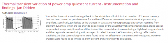
computing thermal distortion
My nose was severely rubbed into bipolar thermal runaway
(a form of extreme distortion) when debugging silicon for
a CAN transceiver IC. At normal VDD (< 5v), the common-emitter
PNP pulldown was robust. Part of IC certification require surviving
Maximum Automobile Battery voltage of 40volts. In every test,
as output was forced from 5volts upward toward 40volts,
the PNP output device self-destructed. Of 5 output transistor
stripes on the IC, the middle stripe showed a burned spot.
The overseas silicon consultant designer balked at considering thermal
runaway as the cause of the failure, so some math was brought
to bear (you may enjoy this).
Assuming bipolars have safe-operating-area failures,
we will compute the failure point (an extreme form of distortion).
This is a case of positive feedback; we'll find the set of
parameters where Gain = 1.000, and we'll know to avoid
operating anywhere near that set of values.
Math:
delta_Temp_result=delta_Temp_in*delta_energy*thermal_resist/watt
By setting delta_Temp_result == delta_Temp_in,
we have the case of Gain = 1.000 as desired.
Now we need delta_energy/dT = delta_Ie/dT * ( Vce * Ie )
delta_Ie/dT = (2milliVolts/1degC) * (10% delta_Ie/4milliVolt delta_Vbe)
and delta_energy = delta_Ie * OperatingPointPower
Now some equation combining:
dT = dT*(2mv/1degC)*(10% delta_Ie/4mv)*(Vce * Ie/100%)*Rthermal
or
dT = dT * 1/20 * Vce * Ie * Rthermal
The current per PNP stripe was 6milliAmps;
I assumed 1,000degC/watt Rthermal, because I had no other value (yet).
dT = dt * 1/20 * 0.006 * Vce * Rthermal
and setting up for Gain = 1.000
1 = 1 * 1/20 * 0.006 * Vce * Rthermal
or
1 = 0.0003 * Vce * Rthermal
we find
3,333 / Rthermal = Vce_runaway
For Rthermal (my assumption) of 1,000 degC/watt,
the Vce needed to cause Gain = 1.000 is 3.3 volts.
However, the measured failure voltage was significantly greater.
Discussing this with an inhouse IC-process-development leader,
I was soon handed an Italian paper guiding me to use, for
the 4micron by 100 micron emitter stripe of the vertical PNP,
a new value for Rthermal of ---- 200 degreeC/watt.
Substituting that, we have 3,333 / 200 = 16.5 volts.
And the consistent Vce of failure, in lab tests, was 15.3 volts.
The team was very happy. The design consultant quickly reversed
their stand about "no. its not bipolar thermal runaway". Some poly
resistors were added, and the CAN Transceiver IC was released.
What is our lesson? If Ie is uncontrolled/unlimited, then bipolar
devices can be operated Vce & Ie values providing ThermalGain = 1.00
and bad things happen to good transistors.
Please note there is no lower limit on the positive feedback.
Any combination of Vce/Ie/Rthermal is + Feedback.
We always get that distortion.
Now consider a bipolar differential pair.
The maximum power is limited because the tail current is limited.
Does that mean there is no thermal distortion?
the info in Fr on memory distortion: La distorsion thermique (Héphaïtos)
A very interesting article about crossover distortion and thermal stability. A handwaved topic, if not just ignored while it is of a paramount importance in my opinion.the info in Fr on memory distortion: La distorsion thermique (Héphaïtos)

many people in here do not believe in memdist, however many claim better sound when use cascoded or cfp pairs at the input...
a little more: La distorsion thermique- tube contre transistor (Héphaïtos)
and L'étage d'entrée de l'amplificateur -1- : étude théorique (Héphaïtos)
well, I do not know FR but understood (hope so
)Attachments
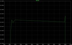
I am glad to see that Thermal track is not so good.
The diode is NOT on the same die, so it is harly better than a diode well thermally bound onto a BJT.
They missed the point, Thermal Track is just a commercial guimick in my opinion.
many people in here do not believe in memdist, however many claim better sound when use cascoded or cfp pairs at the input...
The problem is it's not memory it's thermal distortion. SPICE can be modified to use T, I , and V as independent variables. A first order analysis with fixed Rt/Ct does a lot, but yes heat is a diffusion process. The problem is that the device to device coupling is hard to compute for a discrete circuit. The problem has been solved for IC's in closed form by Alberto Bilotti long ago and there is a very interesting paper in the RCA Technical Journal (?) where they used this to fix an early NTSC color decoder.
I know of no free SPICE that does this but there is an IEEE paper somewhere on how to implement it. I was the EE half of a team implementing it in house but it was not published for the public. This was 25yr. ago already, time flies.
Last edited:
I am glad to see that Thermal track is not so good.
The diode is NOT on the same die, so it is harly better than a diode well thermally bound onto a BJT.
They missed the point, Thermal Track is just a commercial gimmick in my opinion.
My test was with the Sanyo thermal track devices which DO have the diodes on the die.
Jan
Please give my the exact reference of the device, I am very interested.My test was with the Sanyo thermal track devices which DO have the diodes on the die.
Jan
Marc.
http://www.semicon.sanken-ele.co.jp/sk_content/std03n_ds_en.pdf
http://www.semicon.sanken-ele.co.jp/sk_content/std03p_ds_en.pdf
They went through several name- and config changes, as far as I know these are the latest versions. Earlier versions also included the Re of 0.22 ohms on the die, but it was found that on overload, the Re blew to protect the transistor ;-)
Note the difference in diode numbers and type (there's a Schottky in there somewhere).
Edit: here's an app note I used in my design.
Jan
Attachments
Last edited:
I am glad to see that Thermal track is not so good.
The diode is NOT on the same die, so it is harly better than a diode well thermally bound onto a BJT.
They missed the point, Thermal Track is just a commercial guimick in my opinion.
I don't think you should compare the SANKEN devices with the On semi ThermalTrak devices. They are by no means the same thing and are meant to be used in very different ways when it comes to biasing. If the Sanken devices dont work as expected does not mean that the On semi ThermalTrak devices dont work as expected.
I agree that it would be a good thing if the TT diode was on the same die as the BJT, but it is a lot better to have the diode close to the Collector inside the case, instead of glued on top of the plastic case.
All the best
Reodor
soldered to the backplate is a lot better than any location external to the package..............On semi ThermalTrak devices................. it is a lot better to have the diode close to the Collector inside the case, instead of glued on top of the plastic case...........
R.Cordell has written extensively on this and I believe him !
It depends on the relative thermal impedances. The back plate is usually pressed to a heat sink and may be substantially cooler than the junction. The top of the plastic package could easily be closer in temperature to the junction because the plastic can get rid of the heat much less easy as it only has the air as 'heatsink'. Just put your finger on the plastic top; usually much hotter than the heatsink!
I remember reading that if in a class AB amp you mount the bias transistor on the top of the plastic package of the output device, you are actually overcompensating!
Just trying to remember where I read that...
Jan
I remember reading that if in a class AB amp you mount the bias transistor on the top of the plastic package of the output device, you are actually overcompensating!
Just trying to remember where I read that...
Jan
- Status
- This old topic is closed. If you want to reopen this topic, contact a moderator using the "Report Post" button.
- Home
- Amplifiers
- Solid State
- Memory Distortion? and some new beginnings.