You can enter the name of each A, B, and C plot in their respective windows. Once that's done, you save the image as a .png file and the legend goes with it.
See a new post #38 I made at this link:
http://www.diyaudio.com/forums/multi-way/192111-minimum-phase-design-recipe.html#post2642037
See a new post #38 I made at this link:
http://www.diyaudio.com/forums/multi-way/192111-minimum-phase-design-recipe.html#post2642037
Last edited:

yes I always change the name of the measurement to something descriptive otherwise later on I have no idea what is what")
Tony.
Yup, been there - done that!
Carl
A couple quick questions:
Does anyone from HOLM still monitor this thread?
It would be amazingly useful if we could pad SPL in the data export files to actual SPL, this would require more than +99dB for compression drivers.
Can someone post the proper settings to export a correctly formatted frd? I know I have to change the extension from text to frd, I am asking about data format and things like data delimiters.
Thanks!
Hi Dan, see the screenshots below for the settings that I've been using to successfully export holm impulse measurements for use in speaker-workshop.
If you want to increase the level by more than 99db you could try exporting with +99 then import that back and then export again with +whatever. Note that export drops the resolution to 48 khz, if your original measurements are 96Khz or higher you don't get that resolution.
Tony.
If you want to increase the level by more than 99db you could try exporting with +99 then import that back and then export again with +whatever. Note that export drops the resolution to 48 khz, if your original measurements are 96Khz or higher you don't get that resolution.
Tony.
Attachments
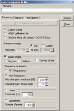
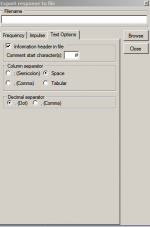
I use a similar output, but with logarithmic at 1024 points. I also usually drop the comments as sometimes they cause trouble importing the file.
Agreed. A better dialog for setting output levels would be great. I believe that ASK, the software's author, no longer monitors this thread. Too bad.
Agreed. A better dialog for setting output levels would be great. I believe that ASK, the software's author, no longer monitors this thread. Too bad.
Measurement problem-No rolloff shown in simple 1st order
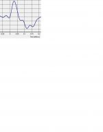
I built several crossovers and upon finishing I wanted to check correct rolloff on woofer and tweeter by using Holmimpulse. But there was not any significant rolloff on my graph. That made me think that perhaps I am not measuring frequency response correctly. In order to verify what I see on Holmimpulse graph I did several measurements using a coil on positive just like on 1st order crossover and was surprised that all lines were going same place-absolutely no roll off; see image.
RED - 1st order with15mh coil should give me 7500 Hz roll off
BLUE- 1st order with 50mh coil should give me 2250 Hz roll off
GREEN- Woofer without coil connected straight to amplifier
Now that I did try both WM60A and laptop microphone as well as reinstalled software could someone please tell me which setting in Homimpulse I should use to get usable data.
No image in your post.
However, how are you independently measuring the woofer and tweeter with the crossover installed?
I can think of two ways to do this. One is to physically place a board between the two drivers. The second is to disconnect one driver - but you still need to present the same impedance load to the crossover.
If you simply disconnect the driver the crossover will no longer work as intended. It may even present a short to the amplifier at some frequencies. Simply substituting a resistor will not work because the driver's impedance varies over frequency. I guess it might get you close, but it might not.
A third option is to place the microphone near field and try that, but near field measurements have their own issues.
One test for sanity sake would be to place the mic at 1 or 2 meters from the source, then take an SPL plot. Next, cover the tweeter with a pillow and repeat. You should see a significant difference. If not, then the issue is with your software and it's setup.
picture attached
Thanks all, picture attached
let me clarify that I am using a coil for this test like a 1st order crossover would be built for the woofer only. No circuit is built for tweeter. Measurement is done from 1 foot distance, I did try up to 10 feet without much difference.


Thanks all, picture attached
let me clarify that I am using a coil for this test like a 1st order crossover would be built for the woofer only. No circuit is built for tweeter. Measurement is done from 1 foot distance, I did try up to 10 feet without much difference.
Thanks all, picture attached
let me clarify that I am using a coil for this test like a 1st order crossover would be built for the woofer only. No circuit is built for tweeter. Measurement is done from 1 foot distance, I did try up to 10 feet without much difference.
View attachment 231959
View attachment 231960
So, is the tweeter disconnected?
How is the coil wired, in series or parallel?
Hi Mycity33, do you have an impedance measurement of the driver under test? It looks like you have calculated both the 2250 and the 7500 coil values using 7 ohms. If that is the DC resistance or nominal impedance of the driver, then it is highly likely that impedance at both of these points is higher than that. If the impedance at 7500 hz is instead 14 ohms then your crossover frequency with a 150uH coil will be much higher than 7.5Khz (closer to 15Khz)
Same sort of thing will occur with your 2.25Khz point. You need to base your coils on the actual impedance at the crossover frequency not the nominal or dc impedance of the driver.
Also some of the drop you are seeing with the 15ouH coil might be due to the coils DC resistance, as if this is high it will have a general attenuation effect.
Tony.
Problem with Time zero Locked alignment
My speaker response in the IR window moves approximately 0.7 cm when I switch from "Detect time zero" (using the "Highest Positive Peak" option) to "Time zero locked" and repeat the measurement. It is always, as expected, centered at 0 when in "Detect time zero" mode. I've made sure that the "Keep in/out stream active" option is enabled.
I first tried using the "Casual Impulse (Analog / IIR Filters)" option, but it would always catch a small "pre-ring" before the main speaker response pulse.
Is it possible I'm overdriving/clipping? I'm using the Mobile-Pre USB box with a Dayton EMM6 microphone. I never see the clip LED come on in the Mobile-Pre, even though I have the input gain turned up 2/3 of the way. Sorry, no pics right now - can supply later.
My overall problem is that I can't reliably measure the acoustic center difference between two speakers as I keep getting different results. I'm hoping the root problem is the shifting I see when switching modes.
Thanks.....
Re: Problem with Time zero Locked alignment
Whoops, the first problem was due to shoddy testing methodolgy (meaning I forgot to re-measure distances accurately ).
).
The other oddity, not having the impulse centered around 0 when using "casual impulse" remains ( see image). Perhaps there are parameters somewhere I could tweak to affect the response analysis.
Whoops, the first problem was due to shoddy testing methodolgy (meaning I forgot to re-measure distances accurately
).The other oddity, not having the impulse centered around 0 when using "casual impulse" remains ( see image). Perhaps there are parameters somewhere I could tweak to affect the response analysis.
Attachments
Hi, I think that causal impulse is actually the least recommended method for detecting time zero. I usually use "Largest positive peak" but you need to pay attention that the signal doesn't need inverting when you use that.
Another trick is to do the detect tme zero twice. On the second attempt it tends to get it right. Once you have measured your tweeter, and made sure time zero is correct, then you can lock time zero and provided you don't move anything measurements of the other drivers will be relative to your tweeters time zero.
Tony.
Where doe´s Holmimpulse store the DAC-ADC file?
Hi Ryssen, on windows XP it is stored under:
C:\Documents and Settings\username\Application Data\HOLM Acoustics\HOLMImpulse\CalibrationDacAdc.cal
It's in a different location on windows7 I can check that when I get home.
Tony.
- Home
- Design & Build
- Software Tools
- HOLMImpulse: Measurements in practice