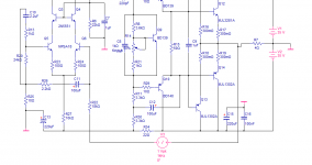
Here is that example I was talking about. I wouldn't build it for myself, but it will get you started.
- keantoken
Hey keantoken,
Per your suggestion, I've been playing around with measuring open loop gain. I don't know for sure, but I think you might have your voltage probe in the wrong place for the type of push-pull amp we've been simulating. I couldn't get it to work right until I moved it like this:

I'm reading the LoopGain2.asc simulation in the examples. Is this also how you read it?
BTW, while figuring out the OLG measurement, I looked at the amp circuit you posted and realized it's exactly the same as the one I was working on except the LTP & driver transistors are the opposite polarity. They're basically identical amps.
Buckeye, that is the correct method AFAIK. Maybe OS is measuring it wrong, I got that schematic from him. Although maybe he started doing it that way because he saw me doing it. In any case, I would go by the loopgain files. I was confused at first by those files, I remember doing it the wrong way for a long time.
Many amplifiers are basically the same. The devil is in the details, the choosing of operating points, the compensation, transistors chosen, grounding, etc. But actually I gave you that file because it was included default with LTSpice, guaranteed to work at first startup.
- keantoken
Many amplifiers are basically the same. The devil is in the details, the choosing of operating points, the compensation, transistors chosen, grounding, etc. But actually I gave you that file because it was included default with LTSpice, guaranteed to work at first startup.
- keantoken
Last edited:
Confused here... what is the correct method, the one I posted or the one you posted? The difference is the feedback path. I think the feedback connection is supposed to be after the probe and from the point of the load. The way push-pull solid state amps are often drawn, it's real convenient to draw the feedback from where the emitter resistors are. But those resistors are what drives the load, so they have to be before the probe. I mean, if you look at the LoopGain2 example, and expand the op-amp, you'll likely see a push-pull pair driving the output. The probe is inserted between the output, which is where the emitter resistors are, and the load. Then, the feedback is taken from the load to the inverted op-amp input. That's the same as the long-tail pair inverting input.
So my point is... you can't put the probe between the LTP (-) base and the emitter resistors. It's got to go on the other side of those resistors. Right?
So my point is... you can't put the probe between the LTP (-) base and the emitter resistors. It's got to go on the other side of those resistors. Right?
Confused here... what is the correct method, the one I posted or the one you posted?
Correct is what is shown in the Mongrel file. It needs to be in the feedback loop as shown. The input needs to be grounded as well.
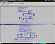
The plot parameters (I don't use LT, so the terms might be off) are something like this: -v(10)/V(33) where V(10) is the net after the probe (on the output side) and V(33) is the net before the probe.
Looks like this:
Attachments


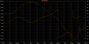
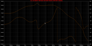
You get a plot that looks like this:...]
Those are nice plots, but the reason I'm doing OLG simulation is to find the phase angle at unity gain. I thought if the phase goes past 180 before unity gain (0dB), the system is unstable. So that's why I'm looking at that. I'm a little confused about how that mongrel simulation does that.
I thought if the phase goes past 180 before unity gain (0dB), the system is unstable.
I can't comment on the LT sim - I don't know how to use it. I 'grew up' on Multisim and I'm used to it's interface. I'm not an expert, by ANY stretch of the imagination, but here's how I understand it:
In the results, the thing to look for is where the gain hits zero db and when this happens, the phase should be close to -100 degrees.

The one I posted earlier was hastily done, for illustration only from a 'work-in-progress' amp. The plot above is close to the real amp.
I can't comment on the LT sim ...
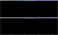
The open loop gain analysis should be the same regardless of which tool you use. What is the proper injection point for the probe? I tried it your way, and the results are similar but not identical.
The top trace is your way, the bottom trace is with the probe between the emitter resistors and the load with feedback going from the load.
Attachments
My guess is that MJL's method is an approximation. In one of my simulations, MJL's method shows a big resonance at around 100MHz, while with the loopgain2 method it doesn't. Don't wanna put the schematic out here though...
In my understanding, -90d is the theoretical optimum, but -100d provides a big performance boost without sacrificing a significant amount of stability. Sort of like the trivial difference between a damping factor of 200 and one of 20000.
- keantoken
In my understanding, -90d is the theoretical optimum, but -100d provides a big performance boost without sacrificing a significant amount of stability. Sort of like the trivial difference between a damping factor of 200 and one of 20000.
- keantoken
My guess is that MJL's method is an approximation.
First, it's not MY method, it's the Middlebrook method of loop gain measurement. Second, it was Andy_c who schooled me on it (OS at the same time, back in his 'frugal amp' thread) and he didn't mention that it was an approximation.
With that said, everything we do in simulation is just that - an approximation. I can say that my Patchwork amp seems to perform as modeled, stability wise.
The first loopgain.asc file uses Middlebrook method, from 1975. The second one says it's "more accurate" and references a paper from 2001.
'More accurate' by how much?
You've no doubt heard the expression 'fruit of the poison tree' - this applies to simulation. Unless your device models are accurate, and the way the simulator implements them is realistic, you can throw any supposed accuracy gain out of the window.
If there is one thing I have learned it's not to blindly trust what the sim is giving as results. Chances are they are just a rudimentary representation of reality.
Last edited:
I've been discussing this with Helmut and Frank Wiedmann in the ltspice yahooo group. They have been very helpful.
I learned that the voltage-only probe as originally shown by keantoken is an apporximation which yields results nearly identical to the Middlebrook results. I see very inconsequential differences at frequencies above a MHz, and none at lower frequencies.
I had another problem in my simulation that made my original results widely different.
On another topic...
Hey MJL, I though of you when working on a fried Carvin R1000 bass amp. It's a monster! No, not because of that. I was surprised to see it used, you guessed it... the MJL12293/21194 pair for the outputs. But I was wondering, have you considered updating your handle to maybe MJL4281, er... no, I mean MJL4302 because I know you're the positive type.")
I learned that the voltage-only probe as originally shown by keantoken is an apporximation which yields results nearly identical to the Middlebrook results. I see very inconsequential differences at frequencies above a MHz, and none at lower frequencies.
I had another problem in my simulation that made my original results widely different.
On another topic...
Hey MJL, I though of you when working on a fried Carvin R1000 bass amp. It's a monster! No, not because of that. I was surprised to see it used, you guessed it... the MJL12293/21194 pair for the outputs. But I was wondering, have you considered updating your handle to maybe MJL4281, er... no, I mean MJL4302 because I know you're the positive type.
Thought so.
Very perceptive of you to spot the positive nature of my persona. I had a tough time weighing the potential benefits of one against the possible drawbacks of the other. NPN seems more manly but has that negative connotation. PNP seems mostly positive but I didn't want to have the 'he has a gay name' label hung off me...
Very perceptive of you to spot the positive nature of my persona. I had a tough time weighing the potential benefits of one against the possible drawbacks of the other. NPN seems more manly but has that negative connotation. PNP seems mostly positive but I didn't want to have the 'he has a gay name' label hung off me...
I used both methods and I've attached OLG plots derived from one of my more interesting designs with each. It may depend on your circuit. Perhaps simulation is not accurate at 100MHz, but if I designed a slower circuit it may be down 40 or 20MHz. The first plot is with Middlebrook and the second is with the newer method. Also of note is that the second method is less optimistic on phase margin.
Square wave plots reveal not a hint of 100MHz resonance, so I conclude the second method is correct. I wouldn't play with accuracy, but I would say it's simply appropriate and that the first method simply isn't, and if the two methods give different results then one must be more accurate than the other, for the input given.
EDIT: used new images to make sure they are both from an identical simulation; this time the amp is driving a BetsyK speaker model.
- keantoken
Attachments
Last edited:
ok, i've done a search and come up empty....
looking for useable models for 2SC2240 and 2SA949. i'm trying to model a certain recent model Onkyo amp, that uses a goofy configuration on the input stage. i say goofy, because at first glance it looks like a current mirror. upon closer inspection, the diff amp (LTP) is cascoded, but the cascode gets it's reference voltage from a voltage divider (two resistors) and not a diode or zener stabilized reference. other transistors used in the amp are 2SC3423, 2SA1360, 2SC2229 2SA933, 2sc3423. there are also 4 "house numbered" devices that i'm going to just take a guess at what they are. but they're drivers and outputs, and it's the input stage i'm trying to figure out.
looking for useable models for 2SC2240 and 2SA949. i'm trying to model a certain recent model Onkyo amp, that uses a goofy configuration on the input stage. i say goofy, because at first glance it looks like a current mirror. upon closer inspection, the diff amp (LTP) is cascoded, but the cascode gets it's reference voltage from a voltage divider (two resistors) and not a diode or zener stabilized reference. other transistors used in the amp are 2SC3423, 2SA1360, 2SC2229 2SA933, 2sc3423. there are also 4 "house numbered" devices that i'm going to just take a guess at what they are. but they're drivers and outputs, and it's the input stage i'm trying to figure out.
I agree. But the issue here is I think simply lack of understanding. Any sort of an electronic/electromagnetic simulator eventually just gets a whole bunch of differential equations and integrates them, and perhaps does a linear system solution too (for FEM). The math behind that is well known, and the shortcomings of numerical approximations are known too, but not in all circles, though. Numerical methods are very hard to get right, that's what science tells us. As soon as you apply them to, say, circuit simulation, it gets even harder.John,
I call the phenomenon Science as Religion (I'll get the Nobel Prize for the concept someday). The irony is intentional. People who treat science as Revealed Truth refuse to question things in a manner precisely analogous to the most fervent religious zealot refusing to face the problems inherent in his faith. And, exactly as one would expect, they condemn most bitterly those who question the underpinnings of their faith as heretics, unbelievers, and worshipers of false gods.
Not to mention purveyors of snake oil.
People who look at a simulation result like if it was holy scripture are simply deeply confused and idolize things that shouldn't be. Something is to be said about trying not to idolize things, no matter if you're religious or not. Simply because something is a result of calculations doesn't mean it's "scientific". Results could be called "scientific" if you follow the strict protocol of fully understanding what's going on at each step of computations, and know the limits of the methods and their impact on the results. This applies to simulations and real-life measurements, too.
On top of that, most simulations are done completely in absence of any input from how the prototype will look like. A state of the art simulation takes into account the physical layout of the prototype. In general, an EM solver is used to get a network of parasitics. Then the network is run through a simplifier, so that instead of tens of millions of Ls and Cs, some very tiny, you get perhaps thousands with saner values that make up an equivalent circuit. And this is run through SPICE. In absence of an EM solver, you use engineering experience and some measurements on a partial prototype to see what the ballparks are. I always look in horror at spice schematics posted in this forum, since it's usually not clear whether, say, decoupling caps have real-life parasitics entered. It's very easy to get milliohm "output impedances" when you use caps that don't exist, traces that don't exist, and generally idealize the heck out of everything... I beg everyone to show the parameter lines for all non-ideal devices on a circuit schematic. Otherwise I can't help but assume they are ideal (no ESR, no ESL, etc), and that the simulation is a pipe dream.
Plenty of models used in simulation are quite simplistic. For example all of the non-generic OPAMPs in LTSpice give rubbish when you run a noise simulation; you have to substitute them with generic library opamps set to equivalent noise densities. And that's just a very basic thing that could have been done right.
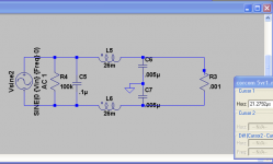
I'm try to simulate a line filter. You'll see my schematic below. I don't know if I'm even close to having a correct schematic relative to how spice sees this circuit. When I just use the inductors and no caps, it wants a ground somewhere, so, I put the ground between the two caps. I can't get much current to pass through R3 regardless of how small a value I place here. Ideally I want to see the behavior with a 3 to 6 amp load. All help appreciated.
Ken
Ken
Attachments
- Home
- Design & Build
- Software Tools
- Spice simulation