Big 'ol pile of scary strong magnets...check.

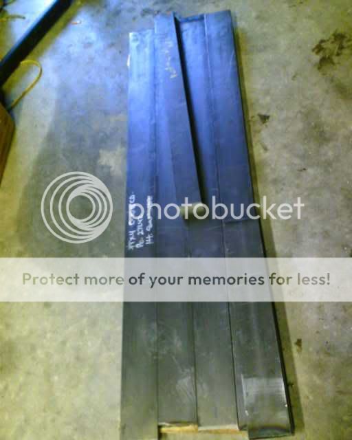
Back breaking pile of steel (250lbs)...check
Finalized design after countless hours of modeling in FEMM, and drafting in cad...check
A dynamic driver design to marry up to it (you can read the thread here, and download the results of Martin Kings Mathcad worksheet here)...check
My new metal bandsaw will be here next week, and I pick up my wood tomorrow. The only piece of the puzzle that hasn't fallen into place yet is my foil. I really want to use 8 micron or less, and am not to thrilled with the idea of harvesting from capacitors. If anybody out there has some to sell, I would love to buy it.
Let the games begin.
Casey
Ribbons
Have a look here at the Apogee replacement ribbons by Graz.
http://www.apogeeacoustics.com/repairsapogeeribbons.html
What was the price on the magnets? and do you really need 3/4" thick side rails? Do you have any links to other ribbon projects?
Thanks;
Bill
Have a look here at the Apogee replacement ribbons by Graz.
http://www.apogeeacoustics.com/repairsapogeeribbons.html
What was the price on the magnets? and do you really need 3/4" thick side rails? Do you have any links to other ribbon projects?
Thanks;
Bill
What was the price on the magnets?
I got a great deal from Supermagnetman.com. He has bundles of factory blems from time to time (minor surface defects), and I bought 150 50mm x 20mm x 12mm N35 magnets for $180.
and do you really need 3/4" thick side rails?
With the amount of flux these bad boys have, anything smaller, and the steel saturates. In fact, modeling the frame I was going to use with some 14mm x 12mm x 6mm magnets with these actually had less flux in the gap than the smaller magnets did due to saturation. As is, I have .6 Tesla across a .8" gap..oofta.
Do you have any links to other ribbon projects?
Read Denis's monster thread here , it covers about all you need to know.
Casey
Well, after waiting 2 weeks for delivery of my new bandsaw (it was supposed to be here in 2 days but the local warehouse was out of stock 😡 ), and then waiting another week for the temp to drop below triple digits, I finally got this project started.
It didn't take long to realize that a saw alone wasn't enough dealing with this large, heavy stock. I needed an adjustable tail feed to support the steel level and true. So building one took up most of Saturday. After that little diversion, I made a series of trial cuts dialing in the saw, then cut the blocks out of the 1" x 3" stock that connect the 2 main pieces of 3/4" x 4" steel...
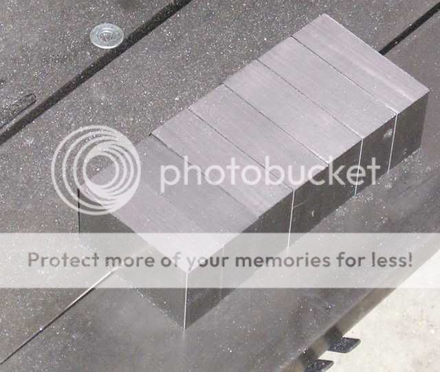
Even though I dialed the saw in well enough to get a consistency of +/- .003", this isn't good enough for these pieces. Also, the surface smoothness is critical for a lossless magnetic circuit. The next step was to true up the pieces, and get a smooth surface on them. I accomplished this on my converted drill press...

I milled all the pieces for 1 ribbon at a time so that they would all be exactly the same. After surfacing one side, I flipped them over and did the other..all the pieces were within my ability to measure consistently.. +/- .0002".
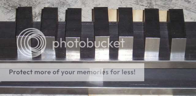
With one set of blocks finished, I decided to mock up the frame to help me visualize the project. I laid out the blocks in 10" increments on 1 side piece (the tape measure is standing in for the row of magnets)...
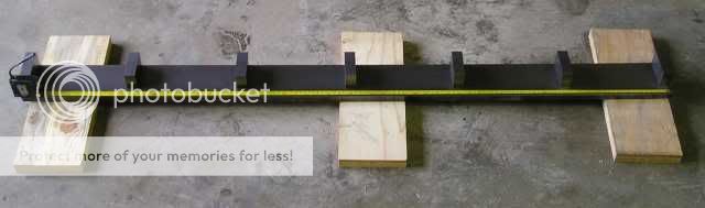
I then laid the other side on...
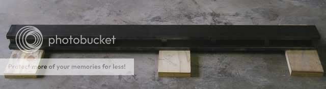
The first thing that struck me is the shear magnitude of this project..the combined weight of the pieces here weigh right at 125 lbs.. Every move has to be thought out ahead of time. The second thing I noticed is that my steel is slightly bowed..this sucks. When I put the other piece on the blocks, I had a gap of around 1/16" on the middle block. I was able to force it down, but this is going to make assembly just a little more fun
The game is on...
Casey
It didn't take long to realize that a saw alone wasn't enough dealing with this large, heavy stock. I needed an adjustable tail feed to support the steel level and true. So building one took up most of Saturday. After that little diversion, I made a series of trial cuts dialing in the saw, then cut the blocks out of the 1" x 3" stock that connect the 2 main pieces of 3/4" x 4" steel...
Even though I dialed the saw in well enough to get a consistency of +/- .003", this isn't good enough for these pieces. Also, the surface smoothness is critical for a lossless magnetic circuit. The next step was to true up the pieces, and get a smooth surface on them. I accomplished this on my converted drill press...
I milled all the pieces for 1 ribbon at a time so that they would all be exactly the same. After surfacing one side, I flipped them over and did the other..all the pieces were within my ability to measure consistently.. +/- .0002".
With one set of blocks finished, I decided to mock up the frame to help me visualize the project. I laid out the blocks in 10" increments on 1 side piece (the tape measure is standing in for the row of magnets)...
I then laid the other side on...
The first thing that struck me is the shear magnitude of this project..the combined weight of the pieces here weigh right at 125 lbs.. Every move has to be thought out ahead of time. The second thing I noticed is that my steel is slightly bowed..this sucks. When I put the other piece on the blocks, I had a gap of around 1/16" on the middle block. I was able to force it down, but this is going to make assembly just a little more fun
The game is on...
Casey
I'll be checking in with your progress as I've bought the magnets more than half a year ago but haven't started yet. 😱
Where did you source the metal? any tips on the femm modeling?
Where did you source the metal? any tips on the femm modeling?
Hi sqlkev
I bought mine from the local Pacific Steel distributor. They only deal in the standard 12' lengths, but since I was buying a fairly large quantity, they special ordered a 3' section of the 1" x 3" stock. Be prepared for "sticker shock"... my steel cost $371.92
I am by no means an expert. I would recommend joining the Yahoo support group. I can give a couple pointers though. One, draft in a separate CAD program and import the DXF file into FEMM if you can..The native CAD in FEMM stinks. Two, remember that FEMM is only 2D, and you can only approximate...it assumes the depth is the same as the width. To model the 3/4" x 4" side rails, for example, I modeled a 1.73 wide rail..a size that is close to the 3 sq. inches the 3/4" x 4" rails.
Casey
Where did you source the metal?
I bought mine from the local Pacific Steel distributor. They only deal in the standard 12' lengths, but since I was buying a fairly large quantity, they special ordered a 3' section of the 1" x 3" stock. Be prepared for "sticker shock"... my steel cost $371.92
any tips on the femm modeling?
I am by no means an expert. I would recommend joining the Yahoo support group. I can give a couple pointers though. One, draft in a separate CAD program and import the DXF file into FEMM if you can..The native CAD in FEMM stinks. Two, remember that FEMM is only 2D, and you can only approximate...it assumes the depth is the same as the width. To model the 3/4" x 4" side rails, for example, I modeled a 1.73 wide rail..a size that is close to the 3 sq. inches the 3/4" x 4" rails.
Casey
Bill08690-
Here is a better (visual) answer to your question. FEMM doesn't have N35 Neo's in it's material library, so I simmed with the N32, and N37, extrapolating the results.
N32..
N37..
As mentioned above, Femm is 2D, so I modeled dimensions of square pieces that have the same cross section area as my rectangular pieces (3 sq. in.). You can see the N32 has .583 T in the gap, and the N37 .617., but more to the point, you can see the steel on the verge of saturating at the corners. I modeled several standard dimensions of steel, and the 3/4" x 4" was the smallest I could get away with.
Casey
and do you really need 3/4" thick side rails?
Here is a better (visual) answer to your question. FEMM doesn't have N35 Neo's in it's material library, so I simmed with the N32, and N37, extrapolating the results.
N32..
N37..
As mentioned above, Femm is 2D, so I modeled dimensions of square pieces that have the same cross section area as my rectangular pieces (3 sq. in.). You can see the N32 has .583 T in the gap, and the N37 .617., but more to the point, you can see the steel on the verge of saturating at the corners. I modeled several standard dimensions of steel, and the 3/4" x 4" was the smallest I could get away with.
Casey
Heavy duty construction
These drivers are going to be something special. Nothing comercially has ever been produced like the ones you are making.
My Apogee Divas weighed 150 lbs for the whole speaker. I imagine you should get very high SPL out of your drivers..
These drivers are going to be something special. Nothing comercially has ever been produced like the ones you are making.
My Apogee Divas weighed 150 lbs for the whole speaker. I imagine you should get very high SPL out of your drivers..
Hey Bill08690,
That is my hope 😉
According to Linesource's effeciency formula, they will be right at 98 dB/W with 8 micron foil (the thinnest I have found so far), and according to linkwitz's dipole spread sheet, they will go 113 dB @ 300 Hz with a .25" excursion 😀
Casey
These drivers are going to be something special
That is my hope 😉
I imagine you should get very high SPL out of your drivers..
According to Linesource's effeciency formula, they will be right at 98 dB/W with 8 micron foil (the thinnest I have found so far), and according to linkwitz's dipole spread sheet, they will go 113 dB @ 300 Hz with a .25" excursion 😀
Casey
Wow, Casey, very very cool and nice. Those ribbons should sound incredible when they're built.
Your design strongly reminds me of one created by Lewis Muratori back in 1994, the Flatline Design Model 175. That speaker used a 175CM ribbon (kapton backed dual foil trace, so still not quite true foil ribbon as yours) that operated from 350Hz to 44kHz. The rest of the speaker employed a 5" midbass driver operating from 350Hz to 100Hz and a 10" side-firing woofer using most of the near 6' tall cabinet in an acoustic suspension design to cover from 100Hz to ~30-35Hz. All crossover points are first order, 6dB/oct, so I believe the ribbons could be brought down even lower (maybe even 100Hz??) with a steeper slope.
Picture (look familiar?):
Side view:
I actually have a pair, the pair of which one is shown in the above picture, up here in Ellensburg, about 40 minutes North of you in Nachos. My pair are currently apart (using the ribbons with a set of Magnepan Tympani bass panels), but I could throw them back mostly together in ~45-60 minutes if you'd like to give them a listen. It might be helpful to give a very similar design a listen to get a feel for how it sounds and any weaknesses so you might be able to improve your design before you start cutting the wood. (Doubt your ribbons could be improved, as those in the Flatlines weigh, oh, about 100lbs less than what you're building.) I found that there were integration issues between such a line source ribbon and a monopole cone midbass. They sounded great within a meter, but the cones' output dropped faster than the ribbons making for an odd imbalance at a normal seating distance. That's why I've switched to the Tympanis to cover everything below 350Hz for better integration and bass. Your welcome to listen to mine to determine if the integration will bother you and even try your electronics out on a similar design.
Say, when you get those built, will you let some of us nearby drop by for a listen of your drool worthy project?
- JP
Your design strongly reminds me of one created by Lewis Muratori back in 1994, the Flatline Design Model 175. That speaker used a 175CM ribbon (kapton backed dual foil trace, so still not quite true foil ribbon as yours) that operated from 350Hz to 44kHz. The rest of the speaker employed a 5" midbass driver operating from 350Hz to 100Hz and a 10" side-firing woofer using most of the near 6' tall cabinet in an acoustic suspension design to cover from 100Hz to ~30-35Hz. All crossover points are first order, 6dB/oct, so I believe the ribbons could be brought down even lower (maybe even 100Hz??) with a steeper slope.
Picture (look familiar?):
An externally hosted image should be here but it was not working when we last tested it.
Side view:
An externally hosted image should be here but it was not working when we last tested it.
I actually have a pair, the pair of which one is shown in the above picture, up here in Ellensburg, about 40 minutes North of you in Nachos. My pair are currently apart (using the ribbons with a set of Magnepan Tympani bass panels), but I could throw them back mostly together in ~45-60 minutes if you'd like to give them a listen. It might be helpful to give a very similar design a listen to get a feel for how it sounds and any weaknesses so you might be able to improve your design before you start cutting the wood. (Doubt your ribbons could be improved, as those in the Flatlines weigh, oh, about 100lbs less than what you're building.) I found that there were integration issues between such a line source ribbon and a monopole cone midbass. They sounded great within a meter, but the cones' output dropped faster than the ribbons making for an odd imbalance at a normal seating distance. That's why I've switched to the Tympanis to cover everything below 350Hz for better integration and bass. Your welcome to listen to mine to determine if the integration will bother you and even try your electronics out on a similar design.
Say, when you get those built, will you let some of us nearby drop by for a listen of your drool worthy project?
- JP
Hi JP,
Thanx, I'm pretty excited about them myself.
They also have a family resemblance to the Apogee Centaur line, another speak that used a acoustic suspension dynamic for the bottom end.
That was my main complaint with the Centaurs. As to how much of this is due to mono vs. dipole I'm not so sure. At 300hz down the monopole "sound" isn't as prounounced, the box "sound" is however. I suspect the real sonic differences lie in the box. To my ear, a TL loaded driver has a very similar sound to dipole..if done right. My room isn't large enough for dipole bass (they will be to close to the back wall), so I went with the TL...I guess I'll find out if I'm right
Damn skippy. I would love to have some different ears grade my effort. We should chat offline to set something up.
Casey
Wow, Casey, very very cool and nice. Those ribbons should sound incredible when they're built.
Thanx, I'm pretty excited about them myself.
Your design strongly reminds me of one created by Lewis Muratori back in 1994, the Flatline Design Model 175.
They also have a family resemblance to the Apogee Centaur line, another speak that used a acoustic suspension dynamic for the bottom end.
I found that there were integration issues between such a line source ribbon and a monopole cone midbass.
That was my main complaint with the Centaurs. As to how much of this is due to mono vs. dipole I'm not so sure. At 300hz down the monopole "sound" isn't as prounounced, the box "sound" is however. I suspect the real sonic differences lie in the box. To my ear, a TL loaded driver has a very similar sound to dipole..if done right. My room isn't large enough for dipole bass (they will be to close to the back wall), so I went with the TL...I guess I'll find out if I'm right
Say, when you get those built, will you let some of us nearby drop by for a listen of your drool worthy project?
Damn skippy. I would love to have some different ears grade my effort. We should chat offline to set something up.
Casey
JP,
I was at work when I replied above, and the picture server was blocked from the network, so I couldn't see them until now. Wow, the resemblance is a little uncanny. I was also a little pressed for time, and didn't reply as thoroughly as I would have liked regarding integrating a dynamic driver to a ribbon. I agree that if you have oodles of power available, and a room large enough for something like your Tympanis, the resulting bottom end is hard to equal. I spent a great deal of time agonizing over the driver choice, and loading arrangement that could compete with a true dipole panel. Having lived with a pair of Maggie MG II's for a couple of years, believe me when I say I understand the charm 😉. Naturally, after settling on the Extremis for it's exceptionally low distortion in the lower midrange, and it's ability to push prodigious amounts of air, Adire had to be so inconsiderate of my needs as to go out of business. Fortunately I had already secured a pair, but now find myself looking for one or two more to stick on the shelf "just in case".
As to your offer to audition your Flatlines, as I am already aware of the integration issues, I am more interested in hearing your current setup..a bar to match, so to speak 😉
Since your email is blocked, I would love to hear from you..just send me a note to the email in my profile. I was starting to think I was the only audiofool this side of the Cascade Curtain 😀
Casey
Whew!! Finished milling the second set of blocks tonight...
I am so glad this phase is complete. Other than perhaps the placing of the magnets, this was the most critical operation..they are the heart of the geometry, and any error here would have caused great heartburn. The second set came to within .001" of the first set, and are more or less indistinguishable from one another.
Next up..much drilling and tapping.
Casey
Hi Casey,
GREAT STUFF!!
Jason Bloom at Apogee knew what he had created when he named his last big all ribbon speaker "The Divas".
I think it will be worth your time to use the free polar response tools to compare marrying your linesource ribbon to both your single driver midwoofer and a line array of 7"-8" midwoofers. All of the cost-no-object speakers I've seen use all linesources and line arrays to maintain a consistent polar and power response. I think if your ears could compare both an all ribbon Apogee with a ribbon+single speaker hybrid you would quickly have an Epiphany.
You could also look at putting a moving mass balanced bipole sub perpendicular in back as a deep bass option that can pressurize your room below the fundamental room mode fequency, which dipoles cannot do.
http://www.pvconsultants.com/audio/frdgroup.htm
Vertical Polar Response: Line Array
Baffle Diffraction Simulator
EDGE The Edge is a simulator for the "baffle step" which supports linesources as well as standard speakers
http://www.tolvan.com/edge/
I used 1080 steel 0.75" x 3" pole pieces, and 1" x 1" rear cross squares every 6" of for my DIY ribbons. This gave a uniform field, modest losses from the front gap stray fields, and enough space to put 0.5" of 705 fiberglass between the ribbon and rear cross bars. My ears think they heard reflections off hard, close rear cross pieces bouncing back to the delicate ribbon. Several ribbon companies emphasis how important it is to avoid rear reflections, and are willing to lose significant gap flux from keeping the pole pieces only as deep as the magnets with completely open rear cavities - no rear magnetic circuit steel cross bars. The Lister patent describes this design. I was almost as worried about stray magnetic fields as I was obtaining a stong field in the gap when I decided to include rear cross steel to complete the magnetic circuit.
I found it valuable to experiment with a front and rear bezel to reduce the edge diffraction from the steel pole pieces.
I converted a junk table saw into a surface grinder for the long pole steel. Good physical protection including magnets are necessary to keep lose filings from mucking up the bearings.
Be REALLY careful with powerful magnets. I never directly touched a magnet and always used non-magnetic tools. I did not trust glue and built an aluminum strip to clamp down the magnets.
Casey,
Not having the experience with the Extremis or hardly any with transmission line designs, I won't argue against your plans. You may very well be right and will come up with an excellent sounding speaker. I'd bet it'll sound even better than expected.
Linesource,
Not to knock Apogees, some folks I put a lot of faith in their hearing swear them to be incredible and I'd love to have one of the largest pairs some day. I just wish folks would call them what they are.
Now please excuse me before I fall off this rickety soap box. 😀
- JP
Perhaps that is so. My assumption was that the difference was more due to dispersion differences between a small, point source driver attempting to mate up to a large line source. As I understand it (and kind of vaguely at that), a line source/array has a vastly different dispersion pattern that results in experiencing less of a drop in output with distance. There's an excellent white paper floating around about these that I really should read again that I believe attributed this in part to the reflections off the floor and ceiling making it seem like a continuation of the line source beyond its limits. The point-source midbass on the other hand experiences the normal drop off with distance that does not match up with the line source making for differences in levels with different seating positions. Then there's the different way it's output is reflected off the surfaces as phantom point sources on each plane interacting. I've absolutely no doubt that you're right in the box adding its own sound to the mix and this is particularly the case with the Flatlines. (Stereophile reviewed them back in the day and found the long panels had three particularly notable resonances that affected the sound.)As to how much of this is due to mono vs. dipole I'm not so sure. At 300hz down the monopole "sound" isn't as prounounced, the box "sound" is however. I suspect the real sonic differences lie in the box.
Er, um, I don't have a room large enough and barely qualify for oodles of power. I've but two SWTP Tigersaurus amplifiers (measured at 270wpc into 8 ohms) on the Tympani bass panels and had a modified Sonic Impact on the ribbons before it finally fried this weekend after a year of use in that application. My room is but 16'x16' with the panels temporarily positioned 7' into the room until I can figure out better positioning. I've only had this hybridized speaker setup for about a week, but thus far I do believe that large dipoles can sound fantastic even in small rooms when some care is taken to placement. You do have to beware of those vintage Magnepans, they have a habit of corrupting the listener. 'Twas a pair of MG-Is that made me a planar fan.agree that if you have oodles of power available, and a room large enough for something like your Tympanis, the resulting bottom end is hard to equal. I spent a great deal of time agonizing over the driver choice, and loading arrangement that could compete with a true dipole panel. Having lived with a pair of Maggie MG II's for a couple of years, believe me when I say I understand the charm .
Not having the experience with the Extremis or hardly any with transmission line designs, I won't argue against your plans. You may very well be right and will come up with an excellent sounding speaker. I'd bet it'll sound even better than expected.
You're more than welcome to. Just be forewarned that I've only had it setup for a week and thus haven't had the opportunity to optimize the positioning, electronics feeding it, or even build a proper crossover for the panels. Not that I don't think it good sounding -- a buddy visited briefly Saturday and ended up camping out on my sofa in front of the stereo for the night and most of Sunday playing favorite tunes, quite the compliment in my mind....I am more interested in hearing your current setup..a bar to match, so to speak
Whoops, I didn't realize I still had that set that way. It's fixed now. Yes, we East Washington audio enthusiasts are few, but proud. Most seem centralized around the Tri-Cities and Spokane, but there are a few around here judging by the audio store that just recently opened in E-burg. I was surprised to see that you were fairly local.Since your email is blocked, I would love to hear from you..just send me a note to the email in my profile. I was starting to think I was the only audiofool this side of the Cascade Curtain
Linesource,
Ack, pet peeve. Apogee was a bit bad about this marketing and many owners persist in calling the speakers "full-range ribbons." The Apogees used a planar-magnetic diaphragm for the bass derived pretty directly from the Blatthaler, ie a sheet fastened on all sides over a bed of magnets. The higher models used quasi-ribbons with foil traces etched onto a Kapton backer suspended between magnets to the sides for the higher frequencies. Only the top models used what I believe the majority here would call a true ribbon such as valveitude is building that consists of corrugated foil suspended between strong magnets on either side. Even the top of the line model, the Grand, used servo-feedback cone subwoofers for most of the bass range. I blame the marketing using this false angle to generate even more interest. It's no wonder people tend to be confused what is a ribbon when Apogee and now even Magnepan call their speakers "full-range ribbons" when only the top models ever used true ribbons and then only for the treble. No wonder I heard someone even call a piezo supertweeter a "ribbon" just a few days ago.Jason Bloom at Apogee knew what he had created when he named his last big all ribbon speaker "The Divas".
Not to knock Apogees, some folks I put a lot of faith in their hearing swear them to be incredible and I'd love to have one of the largest pairs some day. I just wish folks would call them what they are.
Now please excuse me before I fall off this rickety soap box. 😀
- JP
Hi LineSource,
Thank you.
Though I haven't heard both side by side, I have listened to both. I would agree that dispersion patterns played a part in the sound quality differences, but to my ear, the disparity between "open" vs. "closed" (the box) swamped it. I may at some point go with a different configuration with these ribbons, but I have had a "bug" to mate up ribbons to a TL for a l-o-n-g time..I just gotsta know 😀
I played with this some, and got a general idea, but I started playing with it about the time fatigue was setting in with my " paralysis through analysis". Truth be told, after a day of agonizing over baffle steps and such, I compared my baffle design to that of the Centaur Major's, saw that it was damn close, and called it good.
Ya, this is a concern. My cross pieces are spaced 10" apart, for a total of 5 across a 60" ribbon (plus 2 on the ends). They will end up just 1/2" behind the ribbon. To minimize this problem (and I agree it's a problem), I am going to grind the ends facing the ribbon into a "half round", and put a layer of 1/8" Sorbothane (great stuff) over them...this should help considerably.
You betcha!! I have played with them enough to get a good idea of the forces involved..these things can REALLY hurt you if you're not careful.
Casey
GREAT STUFF!!
Thank you.
I think it will be worth your time to use the free polar response tools to compare marrying your linesource ribbon to both your single driver midwoofer and a line array of 7"-8" midwoofers. All of the cost-no-object speakers I've seen use all linesources and line arrays to maintain a consistent polar and power response. I think if your ears could compare both an all ribbon Apogee with a ribbon+single speaker hybrid you would quickly have an Epiphany.
Though I haven't heard both side by side, I have listened to both. I would agree that dispersion patterns played a part in the sound quality differences, but to my ear, the disparity between "open" vs. "closed" (the box) swamped it. I may at some point go with a different configuration with these ribbons, but I have had a "bug" to mate up ribbons to a TL for a l-o-n-g time..I just gotsta know 😀
EDGE The Edge is a simulator for the "baffle step" which supports linesources as well as standard speakers
I played with this some, and got a general idea, but I started playing with it about the time fatigue was setting in with my " paralysis through analysis". Truth be told, after a day of agonizing over baffle steps and such, I compared my baffle design to that of the Centaur Major's, saw that it was damn close, and called it good.
My ears think they heard reflections off hard, close rear cross pieces bouncing back to the delicate ribbon. Several ribbon companies emphasis how important it is to avoid rear reflections, and are willing to lose significant gap flux from keeping the pole pieces only as deep as the magnets with completely open rear cavities - no rear magnetic circuit steel cross bars. The Lister patent describes this design. I was almost as worried about stray magnetic fields as I was obtaining a stong field in the gap when I decided to include rear cross steel to complete the magnetic circuit.
Ya, this is a concern. My cross pieces are spaced 10" apart, for a total of 5 across a 60" ribbon (plus 2 on the ends). They will end up just 1/2" behind the ribbon. To minimize this problem (and I agree it's a problem), I am going to grind the ends facing the ribbon into a "half round", and put a layer of 1/8" Sorbothane (great stuff) over them...this should help considerably.
Be REALLY careful with powerful magnets.
You betcha!! I have played with them enough to get a good idea of the forces involved..these things can REALLY hurt you if you're not careful.
Casey
JP-
There's no arguing your point here..it is valid. There are are a whole host of considerations in this particular attempt..and tradeoffs aplenty 🙂 . As I mentioned in my reply to LineSource, I may decide to go to a dipole linesource for the bottom end at a later date, but my "gut" tells me that a TL midbass/bass will have a sonic signature that will mate well with a ribbon. I will still have the dispersion issues you pointed out, but I'm not convinced yet that they can't be overcome with some mild EQ in the dedicated amps, and some room treatment..I'll know before long.
Yes they can. The room that I had MG II's set up in was about half as large as yours. The placement was so critical that we outlined the base's with tape on the floor once we found the "spot".. a 1/4" off and the image went "poof". Even then, you had to have your head positioned just so. But, it was magic, and we dealt with it this way for 2 years until some Celestion SL-6's found there way in..no Maggie's, but a much better fit to the room.
Store?!? Tell me more about this store of which you speak. The only shop around here is decidedly mid-fi with an emphasis on theater setups.
-Casey
As I understand it (and kind of vaguely at that), a line source/array has a vastly different dispersion pattern that results in experiencing less of a drop in output with distance....The point-source midbass on the other hand experiences the normal drop off with distance that does not match up with the line source making for differences in levels with different seating positions. Then there's the different way it's output is reflected off the surfaces as phantom point sources on each plane interacting.
There's no arguing your point here..it is valid. There are are a whole host of considerations in this particular attempt..and tradeoffs aplenty 🙂 . As I mentioned in my reply to LineSource, I may decide to go to a dipole linesource for the bottom end at a later date, but my "gut" tells me that a TL midbass/bass will have a sonic signature that will mate well with a ribbon. I will still have the dispersion issues you pointed out, but I'm not convinced yet that they can't be overcome with some mild EQ in the dedicated amps, and some room treatment..I'll know before long.
I've only had this hybridized speaker setup for about a week, but thus far I do believe that large dipoles can sound fantastic even in small rooms when some care is taken to placement.
Yes they can. The room that I had MG II's set up in was about half as large as yours. The placement was so critical that we outlined the base's with tape on the floor once we found the "spot".. a 1/4" off and the image went "poof". Even then, you had to have your head positioned just so. But, it was magic, and we dealt with it this way for 2 years until some Celestion SL-6's found there way in..no Maggie's, but a much better fit to the room.
...but there are a few around here judging by the audio store that just recently opened in E-burg...
Store?!? Tell me more about this store of which you speak. The only shop around here is decidedly mid-fi with an emphasis on theater setups.
-Casey
Casey,
No arguing your point either. I'd bet that room treatments will have more of an effect than the dispersion differences and the EQ should help. I biamped my Flatlines trying to boost the midbass to better match the ribbons and found it boomy, but that can easily be attributed to the box sound. I really need to hear what a pair of good transmission lines can do at higher frequencies than just low bass.
The same was the case for my MG-Is for how persnickety they were to set up. I'd get them just perfect and would just lightly bump them while walking by and throw the sound way out of whack. It's surprising how much a fraction of an inch can affect the sound. Fortunately, I've found the ribbons to be much more forgiving for placement, perhaps due to less beaming due to the narrower width. Though, I'm probably more careless about the placement anymore (been undergoing a crisis of faith in my ability to hear these little details that make the difference). If I'm right, then what you're building should be easier to position and get better sound for it. What's not to like?
Store?!? Tell me more about this store of which you speak.[/quote
Yeah, we actually have an audio store from the looks of it, The Audio Attic. This place used to literally be run in the gent's attic at his home just a little bit out of town, but a few months ago I saw a store front open up downtown with the same name. I believe it to be an expansion to become a real store as I've seen B&W mini-monitors and Dalis in the window. Unfortunately, I've not yet chanced to drop by during store hours. E-burg is becoming a big city with its world famous Timothy Hay and now its own real audio store.
😀
- JP
JP-
Well on it's way from a sleepy town to mega-tropolis..shoulda stopped at the hay
Got a little done last night in preparation for the weekends work, and made my first (hopefully last) mistake. I set up my drill/mill table vice as a drill jig to hold my cross-blocks in place for drilling. I ran a spot drill bit to index the drill bit. I spotted one end...

..then turned the block around and spotted the other...

...giving me equally spaced holes on all my blocks...
Which leads me to my error. The end blocks were to be cut in half from 1" x 3" to 1/2" x 3", and the holes should have been indexed a 1/4" in from the sides, instead of the 1/2" of the rest of them...DOH!! I was going to cut the block in order to keep the field uniform down the length of the ribbon. Each group of 10 magnets (5 on each side) share the blocks with the adjacent 10..giving each group half of the block..except the groups on the end. Now, if I cut the blocks in half, I will have a spot that isn't mating to the rail. I will split the difference now, and cut the end blocks to 3/4". This will probably work out better anyway (so I'm telling myself 😀 ) , as the 50mm magnets falls slightly short of the full sixty inches, and will have a magnetic path about 3/16" longer at the ends. The less resistance of the blocks should offset the extra distance of the length.."gilding the lily" here I know.
I'll pick up a fresh, new drill and tap on my way home tonight..don't need to snap a tap off because it was dull.
Casey
E-burg is becoming a big city with its world famous Timothy Hay and now its own real audio store.
Well on it's way from a sleepy town to mega-tropolis..shoulda stopped at the hay
Got a little done last night in preparation for the weekends work, and made my first (hopefully last) mistake. I set up my drill/mill table vice as a drill jig to hold my cross-blocks in place for drilling. I ran a spot drill bit to index the drill bit. I spotted one end...
..then turned the block around and spotted the other...
...giving me equally spaced holes on all my blocks...
Which leads me to my error. The end blocks were to be cut in half from 1" x 3" to 1/2" x 3", and the holes should have been indexed a 1/4" in from the sides, instead of the 1/2" of the rest of them...DOH!! I was going to cut the block in order to keep the field uniform down the length of the ribbon. Each group of 10 magnets (5 on each side) share the blocks with the adjacent 10..giving each group half of the block..except the groups on the end. Now, if I cut the blocks in half, I will have a spot that isn't mating to the rail. I will split the difference now, and cut the end blocks to 3/4". This will probably work out better anyway (so I'm telling myself 😀 ) , as the 50mm magnets falls slightly short of the full sixty inches, and will have a magnetic path about 3/16" longer at the ends. The less resistance of the blocks should offset the extra distance of the length.."gilding the lily" here I know.
I'll pick up a fresh, new drill and tap on my way home tonight..don't need to snap a tap off because it was dull.
Casey
Decided to take a break, and show where I am so far. I actually thought I would have at least one frame more or less together, then things bogged down.
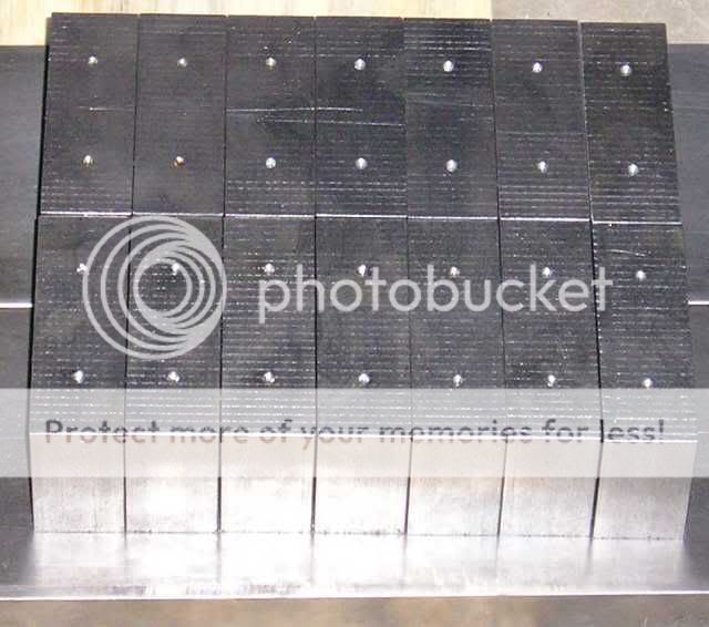
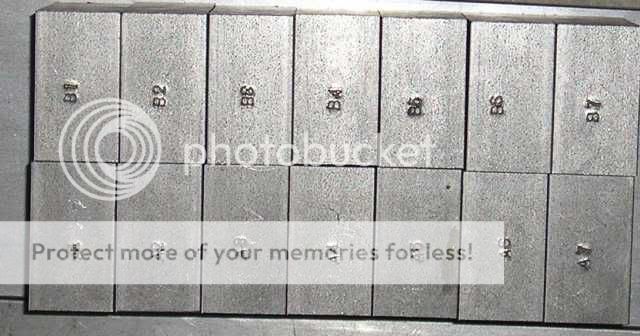
First order of business was to better mark my cross blocks. I had originally just scratched identifiers on them to keep track of which block went where based on the sequence they were sitting in during the milling operation, but after a while the marks were starting to rub thin. I punched them sets "A" and "B" 1-7...
I then chucked up a fresh #29 bit and repeated the drilling process...

I drilled each hole .4" deep. After all the blocks were drilled, it was tapping time. The style of tap you find at the hardware store is designed to tap through a hole..I needed to tap to the bottom of the hole, so I bought a "bottom" tap. Here are the 2 styles to see he difference...

You can see the bottom tap on the right has a blunt end, making starting the thread straight and true a difficult proposition. I used both taps, the standard one to start the thread, and then finished up with the bottom tap with a piece of tape to mark my depth. After tapping my holes (I misspoke earlier when I said 56 holes..actually it was only 28), I ran in my screws to make sure everything worked out...

I got all this done by 10:00 this morning, hence my expectation of getting the frame(s) together..the next step would quench that. As LineSource mentioned, early reflection can be a problem, my solution to mitigate this is to chamfer the ends of my cross blocks facing the ribbon, and then lay down some Sorbothane. The chamfer will refract the sound hitting them, dispersing this energy over a larger area, and "softening" it with the phase shift of the differnt distances traveled (thats the theory anyway). Since I don't have a rounding endmill, or a milling setup that could handle one if I did, I had to do this the old fashioned way. I scribed my radius on the ends, then roughed them in with my bench grinder. Here is were my first time killer came up. About an hour into grinding, the vibration was becoming intolerable. An investigation into the problem showed that my tired, old grinding wheel had worn out of round. Off to the harware store, or rather stores plural. It took me 3 hours, and 30+ miles of store hoping before I found a wheel to fit...sheesh. It took about 2 hours of grinding..counting breaks to let my hands un-cramp..followed by 2 more hours of finishing with a file to get 1 set done. This has been, hands down, the most labor intensive phase of this project. The results are pretty ok though...
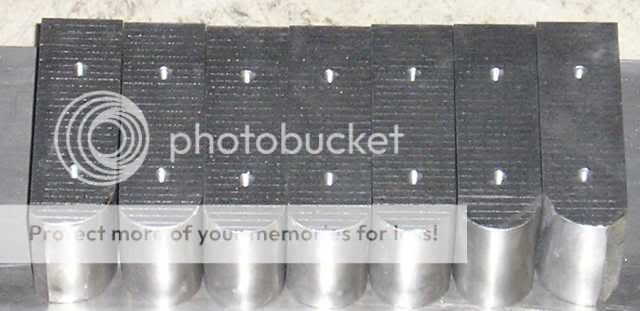
The grind marks on the outside of the end blocks is a boo-boo Fortunately I caught myself before I went to far, and they are in the area that will be cut off anyway.
Well, time to tape up my sore, blistered fingers, and start on the second set...oh joy.
Casey
First order of business was to better mark my cross blocks. I had originally just scratched identifiers on them to keep track of which block went where based on the sequence they were sitting in during the milling operation, but after a while the marks were starting to rub thin. I punched them sets "A" and "B" 1-7...
I then chucked up a fresh #29 bit and repeated the drilling process...
I drilled each hole .4" deep. After all the blocks were drilled, it was tapping time. The style of tap you find at the hardware store is designed to tap through a hole..I needed to tap to the bottom of the hole, so I bought a "bottom" tap. Here are the 2 styles to see he difference...
You can see the bottom tap on the right has a blunt end, making starting the thread straight and true a difficult proposition. I used both taps, the standard one to start the thread, and then finished up with the bottom tap with a piece of tape to mark my depth. After tapping my holes (I misspoke earlier when I said 56 holes..actually it was only 28), I ran in my screws to make sure everything worked out...
I got all this done by 10:00 this morning, hence my expectation of getting the frame(s) together..the next step would quench that. As LineSource mentioned, early reflection can be a problem, my solution to mitigate this is to chamfer the ends of my cross blocks facing the ribbon, and then lay down some Sorbothane. The chamfer will refract the sound hitting them, dispersing this energy over a larger area, and "softening" it with the phase shift of the differnt distances traveled (thats the theory anyway). Since I don't have a rounding endmill, or a milling setup that could handle one if I did, I had to do this the old fashioned way. I scribed my radius on the ends, then roughed them in with my bench grinder. Here is were my first time killer came up. About an hour into grinding, the vibration was becoming intolerable. An investigation into the problem showed that my tired, old grinding wheel had worn out of round. Off to the harware store, or rather stores plural. It took me 3 hours, and 30+ miles of store hoping before I found a wheel to fit...sheesh. It took about 2 hours of grinding..counting breaks to let my hands un-cramp..followed by 2 more hours of finishing with a file to get 1 set done. This has been, hands down, the most labor intensive phase of this project. The results are pretty ok though...
The grind marks on the outside of the end blocks is a boo-boo
Fortunately I caught myself before I went to far, and they are in the area that will be cut off anyway. Well, time to tape up my sore, blistered fingers, and start on the second set...oh joy.
Casey
- Status
- Not open for further replies.
- Home
- Loudspeakers
- Planars & Exotics
- A 60" Ribbon w/TL Loaded Extremis Hybrid