Hi guys
This is going to be a fairly lengthy series of posts, so please bear with me, and hopefully you will accept my apologies for the length and number of posts here. (about 12!) If you have any questions / comments that you’d like to add, do join in. I thought about adding these to the end of the existing threads, but they are getting so long and disjointed, I thought a concise series would be the better bet. Dave –hope some of this might be useful. I’ve included a few observations raised by others here because they are worth repeating and explain quite a few things. I’ve set it in a sort of consecutive order, which was not necessarily originally the case, but helps reading and development.
As some of you might know, I’ve been testing a new version of Martin King’s MathCad worksheets, and I’ve learned a heck of a lot in the process about an enclosure’s behaviour in both anechoic and in-room conditions. Whilst this was related to reflex and MLTL enclosures, much is also applicable to other enclosure types too. As such, I thought it was finally about time I went back to looking at Thor, as I wasn’t happy about some of the original models of the enclosure response graphs I originally came up with –too rough and ready, and I’m now in a better position to interpret the data. So several of the originals will be tweaked, or look very different.
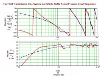
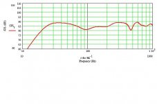
This is my definitive graph of the original Thor’s anechoic frequency response. I thought I’d generate that before I went back to the text of the original article and do a little compare and contrast session, so to speak. To be thorough, this is what was entered.
The worksheet was TL Offset Driver. Driver T/S parameters were those found in the article, with Sd and Vas doubled, and Re and Lvc halved in accordance with the procedure detailed on Martin’s website to account for the twin paralleled drivers. The theoretical driver centre-point was taken as being located at the centre of the tweeter, this being an MTM system, 10.25” down from So. Line-length was 81”, So=1.584Sd, Sm=0.528Sd, the driver centre is 10.25” from So. 0.78lbs ft^3 of stuffing assumed.
I’ll provide some views in Post 2
This is going to be a fairly lengthy series of posts, so please bear with me, and hopefully you will accept my apologies for the length and number of posts here. (about 12!) If you have any questions / comments that you’d like to add, do join in. I thought about adding these to the end of the existing threads, but they are getting so long and disjointed, I thought a concise series would be the better bet. Dave –hope some of this might be useful. I’ve included a few observations raised by others here because they are worth repeating and explain quite a few things. I’ve set it in a sort of consecutive order, which was not necessarily originally the case, but helps reading and development.
As some of you might know, I’ve been testing a new version of Martin King’s MathCad worksheets, and I’ve learned a heck of a lot in the process about an enclosure’s behaviour in both anechoic and in-room conditions. Whilst this was related to reflex and MLTL enclosures, much is also applicable to other enclosure types too. As such, I thought it was finally about time I went back to looking at Thor, as I wasn’t happy about some of the original models of the enclosure response graphs I originally came up with –too rough and ready, and I’m now in a better position to interpret the data. So several of the originals will be tweaked, or look very different.
This is my definitive graph of the original Thor’s anechoic frequency response. I thought I’d generate that before I went back to the text of the original article and do a little compare and contrast session, so to speak. To be thorough, this is what was entered.
The worksheet was TL Offset Driver. Driver T/S parameters were those found in the article, with Sd and Vas doubled, and Re and Lvc halved in accordance with the procedure detailed on Martin’s website to account for the twin paralleled drivers. The theoretical driver centre-point was taken as being located at the centre of the tweeter, this being an MTM system, 10.25” down from So. Line-length was 81”, So=1.584Sd, Sm=0.528Sd, the driver centre is 10.25” from So. 0.78lbs ft^3 of stuffing assumed.
I’ll provide some views in Post 2
Attachments
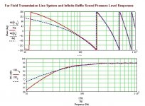
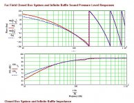
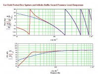
Well, at least there isn’t much ripple. But that’s about all I can say for it. Considering the drivers used I would consider this to be a very mediocre response indeed. Well, let me rephrase that statement: take a look at the picture below. That’s the anechoic response of a sealed box with these drivers, So & Sm =2Sd, 40” tall internally, theoretical driver centre 10.25” from So.
Oh dear oh dear oh dear. Doesn’t look so good for the Thor enclosure as it stands does it? Lets go back to the original article shall we, and have a bit of a reconsidering session. I’m going slowly here, as I’m trying to keep things systematic in my own mind. I have no intention of raising every point that I would take issue with –I haven’t the time or energy to waste doing that, but these are what I consider to be the 5 most significant in this context.
1) It doesn’t exactly get off to a great start by stating that TLs are non-resonant enclosures. I thought they were quarter-wave resonators myself, but there you go. Nor do I remember Bailey, who coined the term TL using a tapered line for that matter.
2) ‘Using two mid-bass drivers exciting the line at slightly different points reduced mid-bass-ripple’. I asked Martin about this, as nothing in his work thus far gives credence to this notion, and I didn’t buy it. I shall quote from his emailed reply verbatim (hope you don’t mind Martin!) ‘I am not sure that this is correct. The standing waves in a TL are independent of driver position. The driver position just determines how much excitation is applied to each standing wave, for example a driver at 1/3 L in a straight TL will not excite the 3/4 mode and will still excite the 1/4 and the 5/4 modes but at a slightly reduced level. The most efficient excitation is at the closed end. My guess is that when I get the two driver TL worksheet running that there will be pluses and minuses for both one or two drivers. I don't see two drivers solving the ripple problem’.
3) ‘The resulting line produces a uniform 3-4db bass-lift from 110Hz all the way down to 20Hz with less than 1db ripple. The -3db point is 44Hz.’ According to MathCad, no it doesn’t, and no it isn’t.
4) Why use alignment tables and then wantonly throw away 1/3 the volume they state is required?
5) Shorting out one driver when measuring the enclosure effectively doubles the internal volume the driver sees. This will produce a different set of results to if both drivers were operating.
Attachments
Ok, so we’re at the same point. What’s going on with this enclosure as it stands? Right, well, before we even begin to think of physical modifications to the enclosure itself, let’s look again at its response, and apply a bit of logic. What do we notice? Well, there’s very little ripple indeed. But hang-fire for a minute: this thing is using 0.78lbs ft^3 of stuffing, uniform, throughout the enclosure. Now, I don’t know about you guys, but I consider that to be excessive in the extreme. Stuffing is only there to damp out those higher harmonics that cannot be engineered out of an enclosure in the design-stages, right? It’s not there to correct other response aberrations. I have a absolute personal limit of 0.5lbs ft^3 of stuffing in an enclosure, and that only from the top to just below the level of the driver, not throughout the entire enclosure. I try to use 0.25-0.3lbs ft^3 if possible. More and the design wants a rethink in my view. What happens when we use too much? Simple: we damage the fundamental resonance that we were aiming to generate in the first place to augment the low end, inevitably causing the bass to slump, and the cabinet to behave like an aperiodic enclosure. There’s easier ways of building one of those, if that’s what you want!
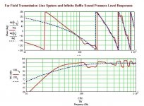
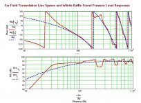
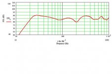
So, let’s try reducing the stuffing and see what happens to the response. Everything else remains consistent with the original design. This is the anechoic response of the Thor enclosure with a uniform stuffing density of 0.1lbs ft^3.
Instant conclusion: Augsperger’s stuffing advice is way off, at least in this case. Whilst very effective at suppressing the higher harmonic resonances, it has clearly grotesquely underestimated the effect such large quantities of stuffing has on the fundamental resonance. As you can see, the bass performance has shot up, though the response is rough (Voigt Pipe owners might think it flat!). I tried adjusting the levels, but there’s no happy medium here sadly. However, existing Thor cabinet owners who want some more bass but do not wish to build another enclosure: experiment with reducing the level of stuffing. Personally, I’d try removing the lot from the second half of the line as a first step, and play around with the levels from there. It could reap dividends, assuming you can cope with the increased ripple. As we key off peaks as a rule, our hearing being amplitude-based, you might not notice in your own room. Try it; you never know, it might work for you. The rest of us need a different approach however.
Attachments
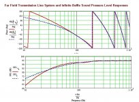
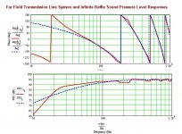
OK, so assuming we wish for some odd reason to stick with the ‘classic TL’, wide So, narrow Sm terminating in free-space geometry, we clearly need to increase the size of the enclosure. So lets revert to the original 0.78lbs ft^3 stuffing, and double the enclosure size and see what happens. So=3.2Sd, Sm=1Sd, everything else remains constant.
Well, it’s better than the original. Just. Not so hot for such a gargantuan enclosure in my view though.
Well, it’s better than the original. Just. Not so hot for such a gargantuan enclosure in my view though.
Attachments
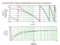
Now, here’s the same enclosure with stuffing reduced to 0.1lbs ft^3. That confirms it. The excessive stuffing specified cripples the fundamental. Of course, it also means that there is more ripple, resulting in quite a jagged response. Bass is sloping away, but that’s fine: one of the things I have learned whilst testing the latest version of Martin’s worksheet is that it is better to have a bass-response that smoothly falls away below 100hz than one that is completely flat. If you’re using a small driver, then a drooping response with a small peak at cut-off is desirable, as this will add weight to the sound, otherwise, a smooth roll-off, otherwise room-gain will come into play, and make for a bass-heavy response, 9 times out of 10. I tend now when working with the anechoic sheets to try for this slowly rolling-off response, or a flat response which I then adjust through altering the port / vent dimensions to achieve this.
I might as well state now that I can’t honestly see any good reason to use the ‘classic’ TL taper, especially when terminating in free-space. The more I work with the MathCad sheets, the more I find I stick with this view. A very high Q and / or Vas driver might be best in this sort of enclosure perhaps, I don’t know, I avoid them, but if that’s the case, they would likely be best on an open-baffle anyway, not a box enclosure.
However, we shall have a stab at an optimised classic enclosure for these drivers, before we try something a bit better, using Martin’s alignment tables and Offset Driver worksheet, which we know to be the most accurate out there. Dave has already drawn one, with the cross-section of the original enclosure doubled, the drivers moved to the position Martin’s tables determines to be optimal, and a floor vent, rather than a high-mounted one, which in my experience is always desirable, coupling better to the room.
Attachments
This is the ‘Fat Thor’ discussed, using 0.1lbs ft^3 of stuffing. Ragged over 100Hz, but the best bass performance of the lot, and with its floor-vent, this beast will THUNDER. Subwoofers will be quaking in terror. Jurassic Park soundtrack? Dark Side of the Moon? No worries here. By the way, you can get similar performance, with 4Hz less at the bottom end, by reducing the size of So to 2.5Sd and Sm to 0.5Sd. Yup, that law of diminishing returns has kicked in. Is that bit more on the bottom end worth such a gargantuan cabinet? Me, I would say not, but that’s up to you.
OK, OK, so assuming that we still wish to use the wide So, narrow Sm geometry for some reason, how the blazes can we reduce that ripple whilst keeping the bass performance propped up? Time to bring on the Mass-Loading technique methinks.
OK, OK, so assuming that we still wish to use the wide So, narrow Sm geometry for some reason, how the blazes can we reduce that ripple whilst keeping the bass performance propped up? Time to bring on the Mass-Loading technique methinks.
Attachments
‘Ere be the tweaked, mass-loaded version of Fat Thor drawn by Dave. Note the massive reduction in the ripple, whilst the bass, although smoothly rolling off (according to the criteria we established earlier) below 100Hz, will, in room, still bellow with the best of them, especially considering that it’s utilising a floor-firing port, which are not known for producing small-gains. I recall some positive comments regarding the in-room bass-performance of this enclosure to the effect that corner placement would be a very bad idea. Excellent.
An increased level of stuffing is possible which also helps in controlling the ripple, which with 1 exception is within +/- 3db. And this is possible with a smaller enclosure: So=2.5Sd, Sm=1Sd. You can prop the bass-up even more if you wish by using a 2” long port rather than the 4” long port specified, at the price of a slight increase in ripple. I doubt you’d need to, but it looks good anechoically.
Enough of this classic geometry however! Lets get to the good stuff: MLTLs are where it is at gentlemen. I like this bit… hope you do!
Attachments
Right, let’s try for a small MLTL enclosure first. Domestic harmony you know… for those with understanding Significant Others, we’ll look at larger enclosures in a minute.
Here’s Small Thor, anechoically. So & Sm=2Sd. 45” long, theoretical driver centre 33.75” from the base. 0.5lbs ft^3 from the top of the enclosure to just below the lower mid-bass driver. Port 2” diameter, 4” long 4” from the base. Front port please guys: my experience in the in-room plots suggests that rear-ports are just looking for trouble. The port is narrower than I’d normally use, but Martin has added a useful little extra facility to the new versions of the sheets that provides a graph of the port velocity, and warns you it it’s going to exceed mach 1. Below that, you should be fine. You could use a 3” port that’s 4” long for a completely flat anechoic response if you wish, but you might well find that the bass-weight becomes excessive.
Here’s Small Thor, anechoically. So & Sm=2Sd. 45” long, theoretical driver centre 33.75” from the base. 0.5lbs ft^3 from the top of the enclosure to just below the lower mid-bass driver. Port 2” diameter, 4” long 4” from the base. Front port please guys: my experience in the in-room plots suggests that rear-ports are just looking for trouble. The port is narrower than I’d normally use, but Martin has added a useful little extra facility to the new versions of the sheets that provides a graph of the port velocity, and warns you it it’s going to exceed mach 1. Below that, you should be fine. You could use a 3” port that’s 4” long for a completely flat anechoic response if you wish, but you might well find that the bass-weight becomes excessive.
Attachments
And here is the Small Thor’s predicted in-room nearfield response, sitting on-axis with the drivers, in a carpeted room, the front baffle a not-unreasonable 36” from the rear wall. I must admit I rather like it.
But you’re an adult now! You want BASS. You want a HUGE enclosure. You want subwoofers the world over to contemplate the meaning of life, the universe and everything. OK, your wish is my command. The Short Thor MLTL cometh!
But you’re an adult now! You want BASS. You want a HUGE enclosure. You want subwoofers the world over to contemplate the meaning of life, the universe and everything. OK, your wish is my command. The Short Thor MLTL cometh!
Attachments
Only a couple more posts left now (sorry once again for the number, one and all, guys!)
Dave drew this beast a couple of months back. For those with large rooms and understanding partners, you could be grinning. So & Sm = 3.2Sd, driver height as per Small Thor, port 4” from the base, 3” wide, 6” long. This baby will need some internal bracing. Anechoic plot runs thus:
Dave drew this beast a couple of months back. For those with large rooms and understanding partners, you could be grinning. So & Sm = 3.2Sd, driver height as per Small Thor, port 4” from the base, 3” wide, 6” long. This baby will need some internal bracing. Anechoic plot runs thus:
Attachments
And here’s the in-room response, as per Small Thor conditions. 25Hz earthquake. For all of these designs, classic TL and MLTL, I’ve assumed the retention of the original 9” external enclosure width so the cross-over BSC won’t need adjusting.
Oh yes –one other thing. I like the base in the original, but it’s not such a hot idea to have a hollow, resonant cavity under the cabinet in my view. If you need them raising, a solid plinth would be better; if it has to be hollow, make very sure it’s extremely solid –doubled panels all round at the very least.
And that, for the moment, is that. Hope some of this is helpful. I’ll think about wide-baffle Thors next, but that’s for another day. In fact, another month, because I need to get my thesis written, as it has to be due in at the end of next month, so I won’t have time for major modelling experiments like this little lot for a few weeks, though I’ll still be lurking around the forum on and off.
Sorry once again this has been such a lengthy series of posts and my very, very best wishes to you all for the New Year! Hope it’s a great 2006 for you all.
Scott Lindgen
(Scottmoose)
Attachments

I'm really looking forward to these new worksheets.
I suffer from a bass heavy room. Having read the original Thor thread, I'm at present experimenting with a conventional TL with a deliberately restricted cross section to roll off the bass, but with close wall/floor loading of driver and port to bring up certain desired frequency areas. (Its a 3-way with very flexible electronics).
I must admit that SAF also has a major influence on the design, and 36" from the wall could not be tolerated.
Looking at your very interesting results, Scottmoose, this does not seem a stupid idea after all, but the new worksheets would avoid the cut and try I am presently using.
Your comment re preference for a slow roll of with a slight kick up at the knee of the curve agrees with experimental real room results.
Good work and most enlightning!
Your effort is worthwhile. It should become required reading for anyone beginning to use the worksheets. I wandered around the simulations at first, not realizing these speakers need room to BREATHE. The Seas units have a 1/2 octave on RS180's, quite impressive.
I'm looking forward to the in-room simulations. I think I'll wait until then to build "finished" speakers.
I'm looking forward to the in-room simulations. I think I'll wait until then to build "finished" speakers.
Which work sheet
Hi,
This thread have fanned my interest in having a go at a ML TL design. But having downloaded the worksheets from the quarter-wave site, I don't know which to start which. The only sheets with parameters for a port are the ported box and MLTQWT sheets. A tappered box is not for me. But the ported box sheet seems to be non-TL. Which is the correct worksheet for a ML TL straight box? Forgive me being an idiot.
Cheers,
KK
kkchunghk asked:
I think the MLTQWT worksheet was developed with the intended use for tapered lines. It serves very well for straight walled enclosures also.
Keep asking questions. I'm glad if I can help.
Which is the correct worksheet for a ML TL straight box?
I think the MLTQWT worksheet was developed with the intended use for tapered lines. It serves very well for straight walled enclosures also.
Keep asking questions. I'm glad if I can help.
Re: Which work sheet
The Ported Box sheet takes into account the standing waves inside the enclosure. During simulations, I have changed the length of the box, while keeping the volume the same, and seen very different responses appear using the Ported Box worksheet. So I do believe you can use the Ported Box worksheet, if you want, as well as the ML TQWT worksheet.
kkchunghk said:Hi,
The only sheets with parameters for a port are the ported box and MLTQWT sheets. A tappered box is not for me. But the ported box sheet seems to be non-TL.
The Ported Box sheet takes into account the standing waves inside the enclosure. During simulations, I have changed the length of the box, while keeping the volume the same, and seen very different responses appear using the Ported Box worksheet. So I do believe you can use the Ported Box worksheet, if you want, as well as the ML TQWT worksheet.
If you are designing an MLTL, I always so my rough calculations in the ML TQWT sheet: it can do any geometry you like, MathCad couldn't care tuppence whether So is smaller or larger than Sm, or both of equal size, it works just the same, so don't worry about that! I sometimes refine a design another sheet if appropriate, but usually it's not necessary. The Ported Box sheet can calculate an MLTL too, but as it's set up differently, for BR designs, it's more fiddly in this context to enter and modify data.
Cheers
Scott
Cheers
Scott
- Status
- This old topic is closed. If you want to reopen this topic, contact a moderator using the "Report Post" button.
- Home
- Loudspeakers
- Multi-Way
- Some Thor models to mull over