Conventional power amplifiers commonly feature a low voltage gain input differential stage followed by a very high voltage gain stage then usually a unity gain emitter or source follower. This design suffers from a distinct topological deficiency that degrades the sound and is responsible for inferior sound quality.
The typical gain distribution is shown in the thumbnail where the weakness of PSRR of the input stage ( not amplifier) due to the divider with stage output Z vs load Z determines intrusion of Class AB PS artefacts which are magnificently amplified by the very high gain Vas to output, blurring the stereo image detail and spatial info and raising the dependance for performance on the PS quality!
Better sound quality from such a design centres around fiddling at the edges of this flawed topology rather than adopting a new one.
Attachments
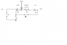
Ignoring the 1K input impedance glitch in the hastily prepared drawing, feedback theory will dictate that this level of intrusion or sensitivity is -
Vs out proportional to A2 x A3/A1 and also to stage load Z/collector Z.
So to reduce this harsh power supply induced output commutation distortion from degrading the sound we need to -
1. Increase A1 without increasing load Z proportionally so CMs are out!
2. decrease A2A3 so the intrusion is amplified less.
So ideally most of the voltage gain should be in the input stage and not in an after injection stage and especially not in a following high gain miller comp stage which degrades load Z as well and results in the typical thumbnail response.
So far so good
Attachments
But Greg.....
Your input stage here is still a diff amp!!
The conventional LTP is a voltage in/current out block; a transconductance configuration. It is the current output which normally drives the voltage amplifier. I find myself agreeing with some of your comments, but your block diagram still does not obviate use of a long tail pair.
Cheers,
Hugh
Konnichiwa,
True, but "diff amps" are the bathwater. They are about 50% of the problem of the generic Amp topology (the rest is the VAS and teh Output stage).
Why not go for complementary folded cascode current feedback topology.
You can get huge amounts of gain in effectively one stage, no common mode induced distortion, you can use good quality complementary J-Fets (2SJ74/2SK170) in the input and if you wanted follow the (single) Input/VAS stage with a BJT Buffered (Emitter follower) Mosfet Output stage
Sayonara
amplifierguru said:We can't throw out the baby with the bathwater here
True, but "diff amps" are the bathwater. They are about 50% of the problem of the generic Amp topology (the rest is the VAS and teh Output stage).
Why not go for complementary folded cascode current feedback topology.
You can get huge amounts of gain in effectively one stage, no common mode induced distortion, you can use good quality complementary J-Fets (2SJ74/2SK170) in the input and if you wanted follow the (single) Input/VAS stage with a BJT Buffered (Emitter follower) Mosfet Output stage
Sayonara

Konnichiwa,
Well, not so much really overlooked, it is a result of using "cut & paste" in a graphics programme to get a general indication.
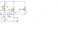
Simply remove the NFB and keep the amplifier open loop, change the feedback application point to the common gates OR change the output stage from common drain to common source for one more inversion, probably a good idea anyway to swap common drain for common source.
Anyway, attached with changed feedback arrangement, you can still use easily 50K...100K input resistors (according to Borberly's work) and then scale the feedback resistor to suit.
darkfenriz said:I see that positive feedback gets very fashionable these days.
MikeB said:That's a good one ! (but darkfenriz was faster)
You might have overlooked that fc-topology is inverting, means you applied a positive feedback, your circuit is not functional at all...
Well, not so much really overlooked, it is a result of using "cut & paste" in a graphics programme to get a general indication.
Simply remove the NFB and keep the amplifier open loop, change the feedback application point to the common gates OR change the output stage from common drain to common source for one more inversion, probably a good idea anyway to swap common drain for common source.
Anyway, attached with changed feedback arrangement, you can still use easily 50K...100K input resistors (according to Borberly's work) and then scale the feedback resistor to suit.
Attachments
Kuei Yang Wang said:........but "diff amps" are the bathwater. They are about 50% of the problem of the generic Amp topology........
But this is completely untrue....
Hi Kuei Yang Wang,
G'day mate.
I disagree with your comment re diff'l amps and find your FET folded cascode impractical to DIY, wasteful of power, requiring multiple supply complexity, ...
Just for some more positive feedback!
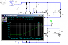
Moving on. From my initial thumbnail pic in post 1, it is fairly obvious that the degradation in PSRR (bode plot) shown in post 2 thumbnail is due to the 3200 x miller C paralleling with the A1 load Z causing the atrocious -30dB at 10KHz. While 2 pole comp instead of the miller C can help, real improvement can be obtained by reducing the gain of the Vas e.g. with R to ground. This intuitively raises the signal level at the injection point relative to the PSR injection. This is probably why the low TIM followers perceive a benefit in loading the Vas.
It becomes fairly obvious that we are just fiddling at the edges of a flawed topology and that the Vas is 50% of the problem.
Cheers,
Greg
G'day mate.
I disagree with your comment re diff'l amps and find your FET folded cascode impractical to DIY, wasteful of power, requiring multiple supply complexity, ...
Just for some more positive feedback!
Moving on. From my initial thumbnail pic in post 1, it is fairly obvious that the degradation in PSRR (bode plot) shown in post 2 thumbnail is due to the 3200 x miller C paralleling with the A1 load Z causing the atrocious -30dB at 10KHz. While 2 pole comp instead of the miller C can help, real improvement can be obtained by reducing the gain of the Vas e.g. with R to ground. This intuitively raises the signal level at the injection point relative to the PSR injection. This is probably why the low TIM followers perceive a benefit in loading the Vas.
It becomes fairly obvious that we are just fiddling at the edges of a flawed topology and that the Vas is 50% of the problem.
Cheers,
Greg
Konnichiwa,
You are familiar with Douglas Selfs work?
If acoording to me the differential amplifier is 50% of the problem and according to you the VAS is the other (which is probably about right, if we keep the output stage sufficiently identical) then if we remove the differential and the VAS we have solved 100% of the problem, works for me.
Sayonara
PS, if we are looking for really high performance (as opposed to tinkering at the edges) seperated, regulated supplies for the frontend several volt in excess of the output stage maximum rails are neccesary, as are suitable means to limit the amount of open loop gain available in case of output overload, so that recovery from clipping is clean, rapid and without "dead zones", so no matter what the rest of my discrete amplifier circuit would look like, the frontend powersupply would allways be seperate as I consider this at least highly desirable, if not essential.
amplifierguru said:It becomes fairly obvious that we are just fiddling at the edges of a flawed topology and that the Vas is 50% of the problem.
You are familiar with Douglas Selfs work?
If acoording to me the differential amplifier is 50% of the problem and according to you the VAS is the other (which is probably about right, if we keep the output stage sufficiently identical) then if we remove the differential and the VAS we have solved 100% of the problem, works for me.
Sayonara
PS, if we are looking for really high performance (as opposed to tinkering at the edges) seperated, regulated supplies for the frontend several volt in excess of the output stage maximum rails are neccesary, as are suitable means to limit the amount of open loop gain available in case of output overload, so that recovery from clipping is clean, rapid and without "dead zones", so no matter what the rest of my discrete amplifier circuit would look like, the frontend powersupply would allways be seperate as I consider this at least highly desirable, if not essential.
Au contraire Kuei Yang Wang,
I find the dill'l input stage perfectly acceptable but I flexible on your complementary SE inputs (mostly needing a servo and have higher THD) and it's the EF or SF output stage that's the other 50% of the problem!
They, in combo with the Vas, are wasteful of supply voltage , and in a power amp that's power. More heating - larger heatsinks, larger x'former for a given power, higher voltage supply C's . Typicall 5V of output power wasted and more with 4 ohms like sub amps where power is a big issue.
But also it's the drive - they need to be driven full swing as they have no voltage gain. No Vas , how to drive them? Simply and from a low impedance that can pull them off for speed.
Cheers,
Greg
Attachments
Mikeks,
I find myself agreeing with you. I have built and tested them all, and a standard diff pair, with single ended VAS using a CCS as collector load, is the best overall gain block I've ever tested.
It has the huge advantage of impeccable offset control, essential with direct coupling; low phase shift; easily compensated high nfb with a ready made fb node, and general uncriticality of configuration. And while the bipolar is not a perfect device, the peculiar combination of current injection and Vbe change at the base of the VAS is very well catered to....
This is but a clear example of technological convergence - which also brought us the front engine-rear drive automobile, the gasring stove, the poppet valve internal combustion engine, the cathode ray tube. That is not to say these approaches cannot be dismissed - JLH, Jean Hiraga, Citroen, Bristol Aero engine company and a host of others have done these things other ways, but you'd better have a very good reason to deviate from the norm. In this connection there is much to be said for nibbling at the edges of existing technology and improving on present topologies with better dimensioning and component selection. It's not sexy, but it can still push the performance envelope.
Cheers,
Hugh
Hi Mikeks,
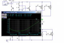
Every topology has it's shortcomings but the pedestrian conventional diff'l-Vas-EF/SF has more than it's share - and in particular, in an energy efficient world of the future (should've been yesterday!), the waste of 7V in an output stage or a 300VA transformer when only a 150W is needed or 30,000uF when only 15,000uF is needed because of PSRR weakness cannot be entertained. Hopefully the days of the audio snake oil salesmen are nearing an end and good design will out.
I would rather listen to the amp below (as I am now) with PSRR shown as I know I'm listening to the music, not the power supply.
That's 40dB or 100 times better than the prev. example and less expensive to build.
Cheers,
greg
Attachments
In playing around with a triple Darlington design, for lower freqs. and lower impedance for a sub and woofer combo, less than 1 or 2 KHz. I find that having a second PS seems to achieve better results. The output stage uses +/-55V. For the front end, I have used a separate much smaller 400mA transformer in a voltage doubler(half wave rectifier) to produce +/- 72V. This then goes through a small regulator circuit to make a clean +/-60V. The 12V difference allows plenty of room to absorb the added ripple from the halve wave. Since this is low current here, there is very little heat to dissipate. Given this circumstance, I don't think the half wave rec. should affect the PSRR that much. The first pre-driver utilizes this PS source. The second driver and outputs use the +/-55V source, unregulated of course. This also can compensate a little for the voltage lost in the 3 pn junctions, re of each device, and the emitter degeneration resistors, and at least keep the first driver out of heavy saturation. well, it you don't push it into hard clipping.
BTW, I'm using a simple single diff pair, well with mirrors, and a CCS loaded VAS. I feel that as ASKA stated, this gives reliable DC offset, which is important here. Since I am not looking for speed in this design, added nfb and miller comp. is not such the drag. The idle sound is quite clean, even through a 5 way speaker! Not much FFIIIZZZZZZZZZ at all. A seperate smaller amp will be used for higher freqs. so this circuit will not be exposed to tweeters, which is were you would here more deplorable fffiiiiizzzzzzz.
BTW, I'm using a simple single diff pair, well with mirrors, and a CCS loaded VAS. I feel that as ASKA stated, this gives reliable DC offset, which is important here. Since I am not looking for speed in this design, added nfb and miller comp. is not such the drag. The idle sound is quite clean, even through a 5 way speaker! Not much FFIIIZZZZZZZZZ at all. A seperate smaller amp will be used for higher freqs. so this circuit will not be exposed to tweeters, which is were you would here more deplorable fffiiiiizzzzzzz.
- Status
- Not open for further replies.
- Home
- Amplifiers
- Solid State
- Simple Killer Amp!