hi all,
I was prepare one set of the Parallel TDA1541A non-o/s DAC Kits.
This kit was very interest. very suitable to use for different size de-coupling caps. All the chips was plug & play.
let take a look for the items for the standard kits.
1. All caps was philips MKP caps.
2. Sanyo OS-con ( aluminium solid caps with Organic
semiconductive electrolyte).
3. all 1% Dale metal film resisters.
4. OFC 2mm thick PCB with Groud plate to low the noise.
5. Digital & analog rectifier cap use Elna high performance series
Gold label caps (25V 3300uf).
6. diode use MBR 160 or Schottky series to lower the noise.
Digital receiver can both use CS8412 or 8414.
Three Analog Output Stage for user choose.
1. 6C45 SE Analog Output Stage with 6X4 rectifier tube.
2. 6DJ8 SRPP Analog Output Stage with 6X4 rectifier tube which
after test by famous Diyer Thorsten's advise( improve the
Lower freq area).
3. AD844 op-amp.
any advise for the kits.
Now I was waiting the test print board to test for the noise.
Any comment for the parts that I choose. I will considerate to change.
thanks
thomas
hi blitz,
thanks for your reply.
this is our diyers website.
www.diyaudiocraft.com.
yes, I was planning to sell in the market. The price will reasonable. When I collect the board. I will take a photo & post to the forum.
this is the I/V stage, three small board for U to choose.
1. 6C45 SE Analog Output Stage with 6X4 rectifier tube.
2. 6DJ8 SRPP Analog Output Stage with 6X4 rectifier tube which
after test by famous Diyer Thorsten's advise( improve the
Lower freq area).
3. AD844 op-amp.
thanks
thomas
parallel
hi blitz,
the price will expensive than mdlover.
U know that all the parts all were choose after I test many times.
I know some of the diyers will choose different grade of parts.
But all the parts that I shows is the standard kits.
The OS-con, Dale all were experience parts.
Diodes too.
I think the estimate price will around USD 200 with all parts.
Is it very reasonable. The main point to design the kits is share erperience to all diyers. Not loss the capital money & had a little profit to support the web is OK. If everyone made the product & aim poit is earn money. NO better good will benefit to diyers.
www.diyaudiocraft.com
thanks
thomas
parallel
Hi Blitz,
the i/v-stage I use will be same as many people use.
The opt stage use a 33R resisters to ground to change I/V. But in my test. I test that use two 75R resisters parallel will be better than one 33R . The noise will be lower.
This experience will be same as I call one computor monther board factory to produce the DAC board. They had skillful to produce full ground layer.
After I test,I considerate use three layers. The middle one is the full ground plate. Although the price of the monther board that use OFC, middle ground plate will be higher. But the rersult is +ve.
So I choose.
this is my opinion.
www.diyaudiocraft.com
thanks
thomas
Hi Blitz,
So, youare not using a passive i/v-stage, but an active and each of these below do the i/v-conversasion ? Cool.
the i/v-stage I use will be same as many people use.
The opt stage use a 33R resisters to ground to change I/V. But in my test. I test that use two 75R resisters parallel will be better than one 33R . The noise will be lower.
This experience will be same as I call one computor monther board factory to produce the DAC board. They had skillful to produce full ground layer.
After I test,I considerate use three layers. The middle one is the full ground plate. Although the price of the monther board that use OFC, middle ground plate will be higher. But the rersult is +ve.
So I choose.
this is my opinion.
www.diyaudiocraft.com
thanks
thomas
I am interested to understand the details, I thought you sell only pcbs ? On the link of your web-page I have not found any information about the kit, can you send me the precise link or more information ?
Why not using an active tube i/v-stage ? Should be even better than passive as the DAC sees only 2-3 ohm than the 33 Ohm of the resistor.
Best Regards
Why not using an active tube i/v-stage ? Should be even better than passive as the DAC sees only 2-3 ohm than the 33 Ohm of the resistor.
Best Regards
parallel
Hi Blitz,
thanks for your opinions.
I was testing the PCB in the last condition( Test Print).
I would like to know that any improvement or not.
I will let U know when PCB final version on hand & will email to U the real board or post in the forum.
Your opinion I considerate already. So I had jumper on the Output stage. Diyer can do by themselves to choose active or passive tube i/v-stage .
This is real diy.
this recent days I was testing the tin foil, copper foil cap in the decouple cap that will effect the sound. I hope more information can give diyer more data to reference.
thanks
www.diyaudiocraft.com
thomas
parallel
hi all,
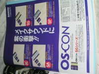
perhaps not too many people know about the sanyo OS-con cap.
This cap is special in digital circuit.
low noise, low esr. with OFC lead out & silver plated.
This is another cap except Elna, & Blackgates that was good for digital use.
This is the best that I can follow with the standard kits.
pls see the photos.
thanks
thomas
hi all,
perhaps not too many people know about the sanyo OS-con cap.
This cap is special in digital circuit.
low noise, low esr. with OFC lead out & silver plated.
This is another cap except Elna, & Blackgates that was good for digital use.
This is the best that I can follow with the standard kits.
pls see the photos.
thanks
thomas
Attachments
Hi Blitz,
BTW, What do you meant by active tube i/v stage? Are you thinking about using tube as a current gain stage, your enlightment please.
Regards
CMT

I don't think the TDA1541a will be happy going into low i/v loading, and you need the i/v resistor around 22-47 ohm to get the voltage out for the next stage.Why not using an active tube i/v-stage ? Should be even better than passive as the DAC sees only 2-3 ohm than the 33 Ohm of the resistor.
BTW, What do you meant by active tube i/v stage? Are you thinking about using tube as a current gain stage, your enlightment please.
Regards
CMT
parallel
hi CMT,
nice to meet U in here.
I think there may be a little misunderstanding.
The tube cannot use to I/V.
Do U agree that my choice the i/V is 33R.
Any recommend was welcome.
thnaks
thomas
www.diyaudiocraft.com
hi CMT,
nice to meet U in here.
I think there may be a little misunderstanding.
The tube cannot use to I/V.
Do U agree that my choice the i/V is 33R.
Any recommend was welcome.
thnaks
thomas
www.diyaudiocraft.com
Konnichiwa,
Good luck. Good digital sound is to at least 50% in correct grounding and PSU decoupling and the TDA1541 is by far from ideal in layout, making the ground layout optimisation for ONE IC a nice challenge. Now doing for two is nothing I'd relish.
Barely okay for decoupling. Look first and foremost at low inductance, secondly on the microphonics. Dielectric et al are modestly unimportant, as the "refresh rate" for these cap's is quite fast.
Fine.
Hmmm. Groundplane is good, AS LONG as you don't use it to close any current loops. If you use the groundplane to also the ground currents from IC's life get's interesting.
More important is the rectifier and the snubering of the transformer parasitic resonance.
Good. Use a "Zobel" across the secondary - R = aparent DCR (primary & secondary) of transformer, Cap as large value as feasible but not so large that significant current flows at 50Hz.
Best is direct coupled, filterless (but use Anti Sin(x)/(x) Filter), transformerless 7308 (Common Cathode stage per channel), biased directly from the -2mA offset of the DAC at a few 100mV, low anode voltage, choke or CCS load. Watch linearity though, this arrangement is a bit critical, the Valve operates near zero bias. But the short chain of: Chip -> Resistor -> Grid (cathode direct to ground) -> Cap from Anode to output works best from where I stand.
Sayonara
siu sin man tho said:I was prepare one set of the Parallel TDA1541A non-o/s DAC Kits.
Good luck. Good digital sound is to at least 50% in correct grounding and PSU decoupling and the TDA1541 is by far from ideal in layout, making the ground layout optimisation for ONE IC a nice challenge. Now doing for two is nothing I'd relish.
siu sin man tho said:1. All caps was philips MKP caps.
Barely okay for decoupling. Look first and foremost at low inductance, secondly on the microphonics. Dielectric et al are modestly unimportant, as the "refresh rate" for these cap's is quite fast.
siu sin man tho said:
2. Sanyo OS-con
3. all 1% Dale metal film resisters.
Fine.
siu sin man tho said:
4. OFC 2mm thick PCB with Groud plate to low the noise.
Hmmm. Groundplane is good, AS LONG as you don't use it to close any current loops. If you use the groundplane to also the ground currents from IC's life get's interesting.
siu sin man tho said:
5. Digital & analog rectifier cap use Elna high performance series
Gold label caps (25V 3300uf).
More important is the rectifier and the snubering of the transformer parasitic resonance.
siu sin man tho said:
6. diode use MBR 160 or Schottky series to lower the noise.
Good. Use a "Zobel" across the secondary - R = aparent DCR (primary & secondary) of transformer, Cap as large value as feasible but not so large that significant current flows at 50Hz.
siu sin man tho said:
Three Analog Output Stage for user choose.
Best is direct coupled, filterless (but use Anti Sin(x)/(x) Filter), transformerless 7308 (Common Cathode stage per channel), biased directly from the -2mA offset of the DAC at a few 100mV, low anode voltage, choke or CCS load. Watch linearity though, this arrangement is a bit critical, the Valve operates near zero bias. But the short chain of: Chip -> Resistor -> Grid (cathode direct to ground) -> Cap from Anode to output works best from where I stand.
Sayonara
parallel
Hi mr. wang.
nice to meet U in here & very thanks to share the experience.
This is the reason why I need to correct many time of the PCB. The ground plate will heavy effect the digital noise, S/N ratio & sound quality.
The Philips MKP is the NOS Blue Box. I testing many de-coupling caps as Wima MKS M-cap silver foil etc. But I still prefer the philips MKP. The 1% MKP philips also very good but expensive. So when I considerate the reasonable price of the kits. I choose this caps. This circuit need 28 pcs of caps. If Use others, i cannot maintain in good price. But i hadn't test the tantulex cap.
Yes, the loops will effect the sound. I reference many DAC's already. The last I freference is the simple Audionote non-oversampling DAC. Use (AD1865) for the ground plate arrangemenbt. Hope the result will good.
The PCB was standard SF4 grade. My friend's factory OEM Sony PCB many year ago. Some of the Hi end items PCB also his factory produce. So why i can get the OFC PCB.
Thanks for your compliment, this several days I was testing the BUV series compare for the MBR & Schottky series. If the price not had too much different, I also will considerate follow with the kits or options.
I agree direct coupled, filterless. But when I testing. I like the choke load for 6c45 much more. CCS I don;t like it although much
linearity.
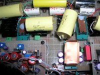
pls see the photos of the prototype.
I try the OPT already which use audio consulting silver wire amophorous core.
The two copper tape cover is the two TDA1541a.
thanks
thomas
www.diyaudiocraft.com:smash: 


Hi mr. wang.
nice to meet U in here & very thanks to share the experience.
Good digital sound is to at least 50% in correct grounding and PSU decoupling and the TDA1541 is by far from ideal in layout, making the ground layout optimisation for ONE IC a nice challenge. Now doing for two is nothing I'd relish.
This is the reason why I need to correct many time of the PCB. The ground plate will heavy effect the digital noise, S/N ratio & sound quality.
Look first and foremost at low inductance, secondly on the microphonics. Dielectric et al are modestly unimportant, as the "refresh rate" for these cap's is quite fast.
The Philips MKP is the NOS Blue Box. I testing many de-coupling caps as Wima MKS M-cap silver foil etc. But I still prefer the philips MKP. The 1% MKP philips also very good but expensive. So when I considerate the reasonable price of the kits. I choose this caps. This circuit need 28 pcs of caps. If Use others, i cannot maintain in good price. But i hadn't test the tantulex cap.
Groundplane is good, AS LONG as you don't use it to close any current loops. If you use the groundplane to also the ground currents from IC's life get's interesting.
Yes, the loops will effect the sound. I reference many DAC's already. The last I freference is the simple Audionote non-oversampling DAC. Use (AD1865) for the ground plate arrangemenbt. Hope the result will good.
The PCB was standard SF4 grade. My friend's factory OEM Sony PCB many year ago. Some of the Hi end items PCB also his factory produce. So why i can get the OFC PCB.
Good. Use a "Zobel" across the secondary - R = aparent DCR (primary & secondary) of transformer, Cap as large value as feasible but not so large that significant current flows at 50Hz.
Thanks for your compliment, this several days I was testing the BUV series compare for the MBR & Schottky series. If the price not had too much different, I also will considerate follow with the kits or options.
Best is direct coupled, filterless (but use Anti Sin(x)/(x) Filter), transformerless 7308 (Common Cathode stage per channel), biased directly from the -2mA offset of the DAC at a few 100mV, low anode voltage, choke or CCS load. Watch linearity though, this arrangement is a bit critical, the Valve operates near zero bias. But the short chain of: Chip -> Resistor -> Grid (cathode direct to ground) -> Cap from Anode to output works best from where I stand
I agree direct coupled, filterless. But when I testing. I like the choke load for 6c45 much more. CCS I don;t like it although much
linearity.
pls see the photos of the prototype.
I try the OPT already which use audio consulting silver wire amophorous core.
The two copper tape cover is the two TDA1541a.
thanks
thomas
www.diyaudiocraft.com:smash:
Attachments
Konnichiwa,
Depends/not quiet. What I strongly recommend however is not to use the groundplane for closing current loops effecting the signal. Yes, this has implications, like for example the requirement for seperate supplies for the receiver and the DAC (then we can use one groundplane and use it as the signal ground as it does not close a supply current loop).
Basically, my vies are:
1) keep current loops controlled and defined.
2) Keep current loops at impedances suited to the task (always low).
3) Keep traces closes to a "groundplane" to lower inductance.
It keeps such things as "ground bounce" and "noisy grounds" to a minimum, something essential (IMHO) for mixed signal circuit with wide dynamic range.
Sayonara
Bricolo said:Thorsten, do you mean that the groundplane musn't be connected to any component? Only one connection to the ground
Depends/not quiet. What I strongly recommend however is not to use the groundplane for closing current loops effecting the signal. Yes, this has implications, like for example the requirement for seperate supplies for the receiver and the DAC (then we can use one groundplane and use it as the signal ground as it does not close a supply current loop).
Basically, my vies are:
1) keep current loops controlled and defined.
2) Keep current loops at impedances suited to the task (always low).
3) Keep traces closes to a "groundplane" to lower inductance.
It keeps such things as "ground bounce" and "noisy grounds" to a minimum, something essential (IMHO) for mixed signal circuit with wide dynamic range.
Sayonara
cmt42001 said:Hi Blitz,
I don't think the TDA1541a will be happy going into low i/v loading, and you need the i/v resistor around 22-47 ohm to get the voltage out for the next stage.
BTW, What do you meant by active tube i/v stage? Are you thinking about using tube as a current gain stage, your enlightment please.
Regards
CMT
Yes, read http://www.ultranalog.com/cdenhancer/cdenhancer1.html
parallel
Hi Blitz,
The ultranalog looks a tube buffer. Hadn't any magnify for the signal.
one of my three small boards ( use 6dj8 ) can change by yourself in SRPP or use one side ot the triode to be the buffer.
But if U choose the 6C45 will not be do in this function because the signal will directly into the grid to magnify.
BTW, if use the buffer stage why I not choose the OP-amp & connect to buffer. I think the diyer will do their right. The Output stage small PCB was seperate in my DAC. Flexible for diyers.
Do it by yourself, share experiences too........................
thanks
thanks again for the opinions. I will collect all & further opinions to further considerate.
But I cannot do all to suitable for all Diyers.
Higher R&D cost will increase the price. I supply all higher grade parts was like to make a cheap but good Simple DAC.
very thanks
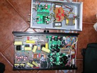
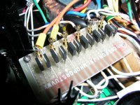
more photo of the prototype to test DAC.
www.diyaudiocraft.com
thomas
Hi Blitz,
tube i/v-stage
The ultranalog looks a tube buffer. Hadn't any magnify for the signal.
one of my three small boards ( use 6dj8 ) can change by yourself in SRPP or use one side ot the triode to be the buffer.
But if U choose the 6C45 will not be do in this function because the signal will directly into the grid to magnify.
BTW, if use the buffer stage why I not choose the OP-amp & connect to buffer. I think the diyer will do their right. The Output stage small PCB was seperate in my DAC. Flexible for diyers.
Do it by yourself, share experiences too........................
thanks
thanks again for the opinions. I will collect all & further opinions to further considerate.
But I cannot do all to suitable for all Diyers.
Higher R&D cost will increase the price. I supply all higher grade parts was like to make a cheap but good Simple DAC.
very thanks
more photo of the prototype to test DAC.
www.diyaudiocraft.com
thomas
Attachments

- Status
- This old topic is closed. If you want to reopen this topic, contact a moderator using the "Report Post" button.
- Home
- Source & Line
- Digital Source
- Parallel TDA1541A non-o/s DAC Kits