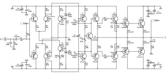
I have found this schematic of a 150W amp
What do you think about that? Is a good amp?
-------------------------------------------------------------
This is one small description that I have found:
A really good amp with an outstanding bandwidth of 1.55MHz and slewrate of 80V/us
Output transistors have been changed to a type that can handle more power.
Also there has been added a separate powersupply for the input stages. This will increase power output for a given supply voltage significantly. A good tip is to separate powersupply for the input stages. You can just run the two powersupply inputs in parallel, and build a separate powersupply for the input stage in the future to acheive a higher power output. In any case the supply voltage for the input should be min. 5 Volts higher than for the output to acheive any real power increase. Run into a 4 ohm load the 150W amp will produce about 300Watts of continous output power. A really excellent amplifier!
-----------------------------------------------------------
Components:
0,33Ù 9w R27-R30
1k Ù R1
2k Ù Pot2
2N5401 T3-T5, T7
2N5551 T1, T2, T6, T8, T9
2SA1358/MJE350 T11
2SA1553/2SA1943 T16, T17
2SA1837 T13
2SC3421/MJE340 T10
2SC4029/2SC5200 T14, T15
2SC4793 T12
3k9 Ù R17
4,7ìF poly C2
4k7 Ù R12, R13
10k Ù R3
10Ù R5-R8, R31
15nF C10
15pF C7, C8
47Ù R23-R26
47ìF 25V C9
47ìF/100ìF 63V C3, C4, C11-C14
100k Ù R2
100Ù R21, R22
100pF C1
200Ù Pot1
220Ù R19, R20
330k Ù R4
330nF C5, C6
390Ù R14
470Ù R11
560Ù R18
680Ù R9, R10
Red D1, D2
100Ù R15, R16
regards
D.N.
Attachments
m60gpmg said:I have found this schematic of a 150W amp
What do you think about that? Is a good amp?
Very similar to the Rotel RB 980 BX...yes!! ....it's a good design!
It's a inverting amp!
")
Just some minor points:
No protection against capacitive loads, either a series resistor
or an inductor, stability into these loads could be an issue.
(may be off the page to the right)
If seperately rectified and smoothed IMO the complication of
providing the extra 5V for the 60V rails is not worth the effort,
unless you can easily find a transformer with the right windings.
.
Doesn't make any sense to me, if anything going over 5 extra volts is pointless.
(Balancing of the input stages and VAS current value looks indeterminate to me.)
sreten
No protection against capacitive loads, either a series resistor
or an inductor, stability into these loads could be an issue.
(may be off the page to the right)
If seperately rectified and smoothed IMO the complication of
providing the extra 5V for the 60V rails is not worth the effort,
unless you can easily find a transformer with the right windings.
.
In any case the supply voltage for the input should be min. 5 Volts higher than for the output to acheive any real power increase.
Doesn't make any sense to me, if anything going over 5 extra volts is pointless.
(Balancing of the input stages and VAS current value looks indeterminate to me.)
sreten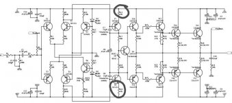
sreten said:Just some minor points:
No protection against capacitive loads, either a series resistor
or an inductor, stability into these loads could be an issue.
(may be off the page to the right)
(Balancing of the input stages and VAS current value looks indeterminate to me.)
About no series resistor or inductor...the stability issue is in my vue is very unlikely...because the output stage is a triple follower ..so the open loop input impedance will be very low.Then the phase shift caused by the capacitif load will be small.
A inductor or resistor at the output allways cause some sound quality degradation..
By the way ...the similar Rotel doesn't also use output inductor ( if memory serves)
About the VAS current value indeterminated...
The current in the LTP is defined by the CCS and cause a voltage drop in the colector resistor...this voltage drop define the voltage of the base of the VAS transistor...and that voltage define de current in the VAS by action of the emiter resistor of the VAS.
So i don't see any reason for this current to be indeterminated.
This kind of VAS biasing is a typical one!
m60gpmg said:There is a problem; in the schematic R15,R16 are 47Ohm but in the component list them are 100Ohm
Which value is better?
Regards
D.N.
With 47 you have higher open loop gain and higher standing current in the VAS stage...whit 100 you have the oposite ,but with increased stability of operation points and more open loop linearity!
Tube_Dude said:By the way ...the similar Rotel doesn't also use output inductor ( if memory serves)
Yes, they used a series resistor instead,
sreten.sreten said:
Yes, they used a series resistor instead,
If they used it....my memory is not what it used to be...
Naim also use a resistor ...0,2 Ohms i think.
Tube_Dude said:
About the VAS current value indeterminated...
The current in the LTP is defined by the CCS and cause a voltage drop in the collector resistor...this voltage drop define the voltage of the base of the VAS transistor...and that voltage define de current in the VAS by action of the emiter resistor of the VAS.
So i don't see any reason for this current to be indeterminated.
This kind of VAS biasing is a typical one!
Well the way I see it the VAS current affects the current sharing
in the LTP's or vice versa, neither the current sharing or VAS
current is fixed as I see it, which is why I said indeterminate.
sreten.Tube_Dude said:About the VAS current value indeterminated...
The current in the LTP is defined by the CCS and cause a voltage drop in the colector resistor...this voltage drop define the voltage of the base of the VAS transistor...and that voltage define de current in the VAS by action of the emiter resistor of the VAS.
So i don't see any reason for this current to be indeterminated.
This kind of VAS biasing is a typical one!
well, try to calculate the current on T7 or T7,
.sreten is right on that one.
sreten said:
Well the way I see it the VAS current affects the current sharing
in the LTP's or vice versa, neither the current sharing or VAS
current is fixed as I see it, which is why I said indeterminate.
No...the VAS current doesn't affect the current in th LTP...it's the oposite in fact, the current in the LTP define the current in the VAS.Via the voltage drop in the colector resistor of the LTP
Tube_Dude said:
No...the VAS current doesn't affect the current in th LTP...
yes, it does. end of the day, the voltage drop off the collector resistor (680ohm for T2) has to be the same as the voltage drop on the base of T7 (Vbe of T7 + voltage drop off R15/47ohm).
Now, try to figure out how much that is,
millwood said:
well, try to calculate the current on T7 or T7,
sreten is right on that one.
Is very easy!!! if yo tell me the voltage drop at the LED of the CCS...actually is this voltage that define all the operation points...

Tube_Dude said:
Is very easy!!! if yo tell me the voltage drop at the LED of the CCS...actually is this voltage that define all the operation points...
pick a number. mine would be 2.8v.
millwood said:
pick a number. mine would be 2.8v.
Well i do your home work!!
Current in the LTP tail 4,6 mA.
2,3 mA in each arm of the LTP.
Voltage drop in the colector resistor of the LTP 1,6 V
Current in the VAS 21 mA .(With 47 Ohms...and 10,5 mA with 100 Ohms)
That's all folks!
Tube_Dude said:Current in the LTP tail 4,6 mA.
2,3 mA in each arm of the LTP.
what makes you think the current in each arm is just 1/2 of the tail current? if that's the case, why do we need current mirrors?
millwood said:
what makes you think the current in each arm is just 1/2 of the tail current? if that's the case, why do we need current mirrors?
Basic electronics!!!
Tube_Dude said:
Basic electronics!!!
it suffices to say that unless that "electronics" is out of this world, you cannot assume that the two arms will split the tail current evenly.
In a typical ltp (with resistors), the current in each arm is determined by the VAS stage. So you would know the voltage drop off R15, plus the Vbe of T7. then you can calculate the current through the 680ohm resistor for T2.
In this case, there is no way to determine the voltage drop off the 680ohm resistor, nor the idle current for the VAS.
not until you use "out-of-this-world" laws of physics,
edit: tube-dude, you may wan tto look into this thread to better understand the issue here.
http://www.diyaudio.com/forums/showthread.php?s=&threadid=16796
Hi folks!
I think Dude is right.
Depending on 47 Ohms or 100 Ohms I also end
up in about 10mA (100 Ohms) or 20mA (47 Ohms).
With respect to the transitortype of T7 2N5401 and its complementary,
I think 100 Ohms are enough. Don't go for BBQ....
The lower current does also match with the fact the there is
a tripple darlington for current amplification.
Cheers
Markus
- Status
- This old topic is closed. If you want to reopen this topic, contact a moderator using the "Report Post" button.
- Home
- Amplifiers
- Solid State
- 150W Is it good?