Warning : It's only simulations !!!
Hi there,
Just for fun, what about some genetic engineering to crossbreed Aleph Ono and Xbosoz ?
I've been contemplating the idea of a fully balanced MM phono stage since the hills were young, but I never had (and still don't have ) the skills to do it.
But never mind, I made an attempt…
I wanted to have it fully balanced from beginning to end. I browsed some web to have an idea of what was awaiting me. Not so simple, uh ? But this fabulous forum gave me some ideas... I found an interesting thread here, about balancing phono cartrigdes, the Xbosoz thread provided me with more dBs, and the Aleph Ono service manual gave me food for thought (thanks Nelson ).
).
Now to the result...
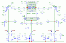
The input stage is the now classical JFET differential pair, with cascoding BJTs. As I didn't want to have a RIAA network inside a feedback loop, since I need 4 of them in a stereo version, I prefered to use the network as a drain load for the diff pair. Idea's not mine, I know... Useful info on this can be found here .
This configuration dramatically drops down the gain of the input stage, so I added a XBosoz after the diff pair, to reach around 45dB@1kHz from input to output.
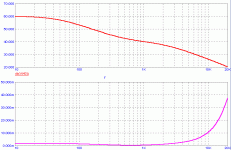
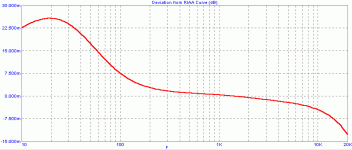
Well, in theory, it should work... The RIAA curve is fitted within +/-0.5 dB above 100Hz, and the interstage coupling caps C1 & C2 filter the LF spectrum below 100Hz, to reach -3dB @ 10 Hz compared to the RIAA curve.
And now I'm coming to you before going to the breadboard, to seek your advice and to listen to your flames .
.
The main point I'm not sure of (added to know whether it will work or not ) is agout the noise level of this beast : is it better to use //ed JFETs at the input, replace the MosFets with NJFet and BJT for the xbosoz folded cascode, etc... ?
And yes, I will have to add some caps for decoupling the biasing stages... Not wanted to overload the schematic
Any comment (improving only ) welcome !
P.S. : A way to calculate the RIAA network can be found here. R1 on the schematic (Figure 1) is the drain resistor (4KOhms) in my case.
And the messy drawing :
Hi there,
Just for fun, what about some genetic engineering to crossbreed Aleph Ono and Xbosoz ?
I've been contemplating the idea of a fully balanced MM phono stage since the hills were young, but I never had (and still don't have
But never mind, I made an attempt…
I wanted to have it fully balanced from beginning to end. I browsed some web to have an idea of what was awaiting me. Not so simple, uh ? But this fabulous forum gave me some ideas... I found an interesting thread here, about balancing phono cartrigdes, the Xbosoz thread provided me with more dBs, and the Aleph Ono service manual gave me food for thought (thanks Nelson
Now to the result...
The input stage is the now classical JFET differential pair, with cascoding BJTs. As I didn't want to have a RIAA network inside a feedback loop, since I need 4 of them in a stereo version, I prefered to use the network as a drain load for the diff pair. Idea's not mine, I know... Useful info on this can be found here .
This configuration dramatically drops down the gain of the input stage, so I added a XBosoz after the diff pair, to reach around 45dB@1kHz from input to output.
Well, in theory, it should work...
And now I'm coming to you before going to the breadboard, to seek your advice and to listen to your flames
The main point I'm not sure of (added to know whether it will work or not
And yes, I will have to add some caps for decoupling the biasing stages... Not wanted to overload the schematic
Any comment (improving only
P.S. : A way to calculate the RIAA network can be found here. R1 on the schematic (Figure 1) is the drain resistor (4KOhms) in my case.
And the messy drawing :
Attachments
Hi Cheff ,
beautiful subject, I'm glad that someone give it a try
The way is obtained the RIAA curve is absolutely interesting .
I myself made some experiments some times ago.
I feel to add that without input transformers the thing is unacceptable , lots of noise picks up .So the diff pair at the input must be a unbal/bal converter . To do this one input has to be grounded .
Please someone correct me if I'm wrong
beautiful subject, I'm glad that someone give it a try

The way is obtained the RIAA curve is absolutely interesting .
I myself made some experiments some times ago.
I feel to add that without input transformers the thing is unacceptable , lots of noise picks up .So the diff pair at the input must be a unbal/bal converter . To do this one input has to be grounded .
Please someone correct me if I'm wrong

Thanks gentlemen, glad to have raised some interest 
stefanobilliani
First, it also works with unbalanced cartriges. As you say, just ground one input of the diff pair. But I'm not sure to understand what you mean by your "noise pickup" issue. Most of cartridges are in fact balanced, and the ground connection that ties the two grounds of the cartridge's coils is done in the cartridge shell (at least on mine ). See here a nice post by GRollins about that. In my mind, balancing all the stuff from input to output had the advantage of noise cancellation... Am I wrong ?
jam,
Yes I saw your posts and links on the thread I mentionned above. And I sure was inspired by Allen Wright's approach for RIAA eq. Re. // Jfets at input, I surely will do something like that, but I'm not sure that the noise will dramatically decrease : I would have to decrease the drain current to 2.5mA for each Fet, and according to the 2SK289 datasheet, the noise of each Fet with increase a little if the drain current is reduced... But I still think the overall noise should decrease.
Also about noise, I'm not sure MosFets are the best performers here for noise, and I was considering using another 2SK389 JFet instead of the IRF610, and making the folded cascode with a BJT. Simulations I have made showed it could be possible, but I have no clue about the noise performances comparison of these two topologies... Any hint ?
Buffering outputs is also tempting, but I was a little bit reluctant to add devices in the signal path... Are these buffers really necessary ?
stefanobilliani
First, it also works with unbalanced cartriges. As you say, just ground one input of the diff pair. But I'm not sure to understand what you mean by your "noise pickup" issue. Most of cartridges are in fact balanced, and the ground connection that ties the two grounds of the cartridge's coils is done in the cartridge shell (at least on mine

jam,
Yes I saw your posts and links on the thread I mentionned above. And I sure was inspired by Allen Wright's approach for RIAA eq. Re. // Jfets at input, I surely will do something like that, but I'm not sure that the noise will dramatically decrease : I would have to decrease the drain current to 2.5mA for each Fet, and according to the 2SK289 datasheet, the noise of each Fet with increase a little if the drain current is reduced... But I still think the overall noise should decrease.
Also about noise, I'm not sure MosFets are the best performers here for noise, and I was considering using another 2SK389 JFet instead of the IRF610, and making the folded cascode with a BJT. Simulations I have made showed it could be possible, but I have no clue about the noise performances comparison of these two topologies... Any hint ?
Buffering outputs is also tempting, but I was a little bit reluctant to add devices in the signal path... Are these buffers really necessary ?
Despite the huge interest for this kind of design  , I'm still on the run
  .
.
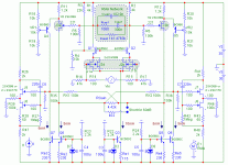
I modified the schematic to include Fet buffers at the output, used a Jfet/BJT folded cascode instead of a full-mosfet one, removed the coupling caps, doubled the input fets, and modified the topology a bit .
.
I previouly mentionned that I had a deviation from the RIAA curve of more than 1.5dB for low frequencies, and thought the coupling caps where guilty. So I tried to remove the caps, but the deviation was still here. It finally appeared that this behavior was related to the two feedback loops (Rfb1 & Rfb2 on the first schematic). But I don't know why.... Can someone explain to donkey-me what happened here... ? Now the theoretical RIAA deviation is below 0.04dB
So I modified the topology to include the now famous X feedback, and we have here the new schematic. It's DC coupled, and output offset is nulled using VR1 & VR2. Gain at 1kHz can be selected "as usual "by adjusting the source-to-source resistor. Here a jumper can help to switch between 40dB and 60dB.
Before I draw the actual schematic of the beast I want build, may I be bold enough to ask you if you see any flaws in this design ?
I modified the schematic to include Fet buffers at the output, used a Jfet/BJT folded cascode instead of a full-mosfet one, removed the coupling caps, doubled the input fets, and modified the topology a bit
I previouly mentionned that I had a deviation from the RIAA curve of more than 1.5dB for low frequencies, and thought the coupling caps where guilty. So I tried to remove the caps, but the deviation was still here. It finally appeared that this behavior was related to the two feedback loops (Rfb1 & Rfb2 on the first schematic). But I don't know why.... Can someone explain to donkey-me what happened here... ? Now the theoretical RIAA deviation is below 0.04dB

So I modified the topology to include the now famous X feedback, and we have here the new schematic. It's DC coupled, and output offset is nulled using VR1 & VR2. Gain at 1kHz can be selected "as usual
Before I draw the actual schematic of the beast I want build, may I be bold enough to ask you if you see any flaws in this design ?
Attachments
Thanks Jam.
Yes I'm going to try to build one . Just to hear the tremendous background noise it will make
  .
.
Since it looks good to you (and others ?) , I will draw an actual schematic with actual values for the RIAA network, proper decoupling caps, input capacitance switches, and other goodies...
Just a few things I'm not sure of : I love LEDs for CCS - they glow in the dark -, and in the ones I usually build, the LED is thermally coupled to the BJT(s), decoupling caps for each led are a 100uF 'lytic bypassed by a 100nF film cap. Instead of a resistor, The led is fed by a source degenerated Jfet (J108 or others) to provide it with constant current. But I'm wondering here if it is the best choice for low noise levels... Any hints ?
And the other thing is that I wonder if sources resistors for the //ed input Jfets are necessary in the "real life" ? Do I have to add some ?
Mosfet output buffer is looking nice - I love the sound of heavily biased Mosfets -, so I will try to plan a PCB allowing to test the two types of buffers. Thanks for the idea
Yes I'm going to try to build one
Since it looks good to you (and others ?) , I will draw an actual schematic with actual values for the RIAA network, proper decoupling caps, input capacitance switches, and other goodies...
Just a few things I'm not sure of : I love LEDs for CCS - they glow in the dark
And the other thing is that I wonder if sources resistors for the //ed input Jfets are necessary in the "real life" ? Do I have to add some ?
Mosfet output buffer is looking nice - I love the sound of heavily biased Mosfets -, so I will try to plan a PCB allowing to test the two types of buffers. Thanks for the idea
CheffDeGaar, nice work (in theory). I see that you like something glowing, me too, but LED's aren't so predictable in voltage. Can go from 1.4-1.8 Volts, for red ones. I would go for one powerful voltage reference for all cuurent sources A LM431 maybe, with separate LP-filters for each transistor. 47-100 k + 100nF-10 µF. With this filter, it's much easier to filter out noise.
I have certain doubts about balanced pick signal going into a amp which aren't very good in rejecting common mode noise. This is only a hunch.
Have you checked http://www.klaus-boening.de/html/laboheme.html/]Klaus Böning's[/URL] balanced vinyl amp?
I have certain doubts about balanced pick signal going into a amp which aren't very good in rejecting common mode noise. This is only a hunch.
Have you checked http://www.klaus-boening.de/html/laboheme.html/]Klaus Böning's[/URL] balanced vinyl amp?
The problem you are likely to encounter is that both imputs of the cartridge will be able to pick up all manner of stray noise from the environment. If the common mode rejection figure of your input is high enough, it won't matter, but if it's not, the result is likely to be noisier than an unbalanced connection.
Peranders,
Thanks. I know red LEDs (the ones I use) have a dispersion in forward voltage. But I have about 500 of them. Mine give about 2V for Vf. They're rectangular so they feel comfortable on a TO92 or T0220 BJT case. I always select the LEDs prior to building to have the same forward voltage under the same current (the one that is planned in the future design).
But I will sure investigate the common voltage reference solution, and the LP filter is a very nice idea to consider.
Sure ! I linked his site on my first post in this thread
Mr Pass,
Thanks for feedback (pun intended ). Yes I have read on this forum (couldn't find where again...) that you don't like balanced phono inputs a lot
  But I wanted to be able to test, and I still have the possibility to ground one input. I had once the opportunity to compare both connections on a friend's balanced tube phono preamp, and simply switching from unbal to bal input with the same turntable was amazing ! But I surely won't be as lucky as my pal, and will hear a huge "HMMMMMMMM"
Thanks to all for passing by.
Thanks. I know red LEDs (the ones I use) have a dispersion in forward voltage. But I have about 500 of them. Mine give about 2V for Vf. They're rectangular so they feel comfortable on a TO92 or T0220 BJT case. I always select the LEDs prior to building to have the same forward voltage under the same current (the one that is planned in the future design).
But I will sure investigate the common voltage reference solution, and the LP filter is a very nice idea to consider.
Have you checked Klaus Böning's balanced vinyl amp?
Sure ! I linked his site on my first post in this thread
Mr Pass,
Thanks for feedback (pun intended
 But I wanted to be able to test, and I still have the possibility to ground one input. I had once the opportunity to compare both connections on a friend's balanced tube phono preamp, and simply switching from unbal to bal input with the same turntable was amazing ! But I surely won't be as lucky as my pal, and will hear a huge "HMMMMMMMM"
 Thanks to all for passing by.
Cheff,
I once brought up this idea with Mr.Pass and all he said that I required was a cartridge with a center tap for each coil.
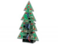
I am glad you like to use LED's for biasing circuits. Fred likes LED's as well. Here is a picture of Fred's amplifier board.


Regards,
Jam
P.S. Yup! It lights up like a Christmas tree.
I once brought up this idea with Mr.Pass and all he said that I required was a cartridge with a center tap for each coil.
I am glad you like to use LED's for biasing circuits. Fred likes LED's as well. Here is a picture of Fred's amplifier board.
Regards,
Jam
P.S. Yup! It lights up like a Christmas tree.
Attachments
CheffDeGaar, I think kind of industrial. Is it possible to design in precision instead of selecting (cost money)? I your case it's very easy to design in precision in currents. If you use for instance a 431 and set the voltage to 5-8 volts, then you will have a pretty stable current in all stages. A led can be put in series with the current sources if you want some "glow".
If you want to go extreme (and maybe enhance the common mode rejection) use cascodes.
If you want to go extreme (and maybe enhance the common mode rejection) use cascodes.
Back on the block 
Well, thanks to all of you for your constructive comments. I have revised my copy, and here is the version I'm currently drawing a PCB for.
Not a lot of changes though. I have given up with the LED-based CCS, and I use now a single precision voltage reference fed by a current source.
J508 current sources are also used to provide a stable bias to the folded cascode BJT. I found that the output offset was very sensitive to this bias voltage, and I wanted to reduce the possible drifts. But If any of you has a better solution to get a nice bias for this folded cascode, pleaaaaase tell me
Some parts values have been modified a little, mainly to match what I had in my junkbox . CCS BJTs have been swapped for more powerful ones (dissipated power is about 250mW in Q3). The RIAA Network is made of available (for me) values, and RIAA response is more than fine (will post a plot of it soon).
I've included the power supply I plan to use. It's very very similar to the Pearl's one , but if you know a better one, I'll take it !
Lots of decoupling caps on the schematic, so no picture (too big), but a PDF instead.
Comments or flames very welcome.
Enjoy.
Well, thanks to all of you for your constructive comments. I have revised my copy, and here is the version I'm currently drawing a PCB for.
Not a lot of changes though. I have given up with the LED-based CCS, and I use now a single precision voltage reference fed by a current source.
J508 current sources are also used to provide a stable bias to the folded cascode BJT. I found that the output offset was very sensitive to this bias voltage, and I wanted to reduce the possible drifts. But If any of you has a better solution to get a nice bias for this folded cascode, pleaaaaase tell me

Some parts values have been modified a little, mainly to match what I had in my junkbox
I've included the power supply I plan to use. It's very very similar to the Pearl's one
Lots of decoupling caps on the schematic, so no picture (too big), but a PDF instead.
Comments or flames very welcome.
Enjoy.
Attachments
I'm going to learn that for recognize an X circuit , the expertize is not enough  for me , and when you think you learn it , then something new comes

Between your previous schematic and this last one , I see a different metod for the X results:
before (in the second stage) the X was obtained like the Nelson's
patent shows; now the resistors from the folded cascode outputs
goes to the sources of the j-fets forming a graphic X so that the-phase-inverted output is attached at the-sources-in phase

Won't you please explain the motive for this change?
Thanks in advance
 for me , and when you think you learn it , then something new comes
 Between your previous schematic and this last one , I see a different metod for the X results:
before (in the second stage) the X was obtained like the Nelson's
patent shows; now the resistors from the folded cascode outputs
goes to the sources of the j-fets forming a graphic X so that the-phase-inverted output is attached at the-sources-in phase

Won't you please explain the motive for this change?
Thanks in advance
Hi stefanobilliani
I must admit I do not quite understand the first part of your question. The topology is globally the same as in the previous schematic (post #5 of this thread). I don't see a huge difference, sorry... Misunderstanding ?
And if I don't abuse me, the output of one folded cascode and the source of the opposite JFet are in phase....
Did I answer your question ?
I must admit I do not quite understand the first part of your question. The topology is globally the same as in the previous schematic (post #5 of this thread). I don't see a huge difference, sorry...
 Misunderstanding ?
And if I don't abuse me, the output of one folded cascode and the source of the opposite JFet are in phase....
Did I answer your question ?
Both too quick 
Well, I explained in post #5 that I had some problems with this feedback loop... I still don't understand why it has such a bad effect on the low frequency response.... Thus I came back to more conventionnal design And I don't know if it's an "X"... Seems to work nicely without Rx1 and Rx2.
Cheers
Well, I explained in post #5 that I had some problems with this feedback loop... I still don't understand why it has such a bad effect on the low frequency response.... Thus I came back to more conventionnal design
Cheers
- Status
- This old topic is closed. If you want to reopen this topic, contact a moderator using the "Report Post" button.
- Home
- Amplifiers
- Pass Labs
- Balanced MM phono stage : When Aleph Ono and Xbosoz meet...
