It’s been a while since I started a thread about a full-blown project. This one has a somewhat more involved back story than most—it goes something like this:
When I was in college there was this amplifier called the Mark Levinson ML-2. For anyone who might not be familiar with it, the ML-2 was a 25W class A monoblock. It was large for its output, ran hot, and cost a young fortune. Being young myself, I didn’t have the requisite fortune to buy a pair. Such is life.
The low output wattage was a problem, too. Back then I needed (or put more precisely, wanted) power and lots of it. I listened mostly to rock and expected it to be at concert volumes. I don’t recall owning an amp less than 100W/ch during that period and most were higher powered.
Even though it was unattainable, something about the concept of that amp stuck with me. It was portrayed as a spare-no-expense assault on the state of the art. Yes, that’s a common theme in audio literature, but this one was more believable than most. The class A thing was pretty rare in those days (and with the exception of some of Nelson Pass’s stuff, it still is). The use of premium quality parts was unusual. I know this may sound like something out of the Stone Age, but it was nothing in those days to open up a piece of ordinary equipment and see 5% or 10% tolerance resistors. If that doesn’t make you feel faint, then I’ll apply the coup de grace and let you in on a little secret…there were such things as 20% resistors back then, and yes, you’d sometimes see them in audio gear. Along came the ML-2 proudly sporting 1% resistors and it was near enough miraculous that grown men swooned. Suffice it to say that the thing was as near a Ferrari as the audio world had to offer—built to exacting tolerances, hotter n’ hell, and high performance, all in black anodized chassis roughly the size and weight of a VW Beetle.
Time passed. My fortunes rose and fell (not the financial kind unfortunately, that’s just a figure of speech), my audio system went from bi-amped to tri-amped, and my listening habits trended somewhat lower in volume. Just about the time I was beginning to think I might be able to justify such a gloriously impractical thing as a 25W amp for my mids and highs…they went and discontinued the confounded thing. Aaargh!
More time passed and I began to build more of my own circuits. Then something unexpected happened…I stumbled upon www.marklev.com and discovered not only the schematics for the ML-2 itself, but the schematic for something called the JC-3, the prototype for the ML-2. Now, I’m sure everyone in the world knew this but me, because the schematics had appeared some time back in The Audio Amateur, but I’ve never had a subscription to any DIY publication; it’s as much as I can do to build the ideas I come up with—I certainly don’t need even more things added to my to-do list. Suffice it to say that although I knew John Curl had designed the amp, I had been unaware that it had been redesigned by Tom Colangelo on its way to the production line.
After the unnecessarily complex ML-2 schematic, the JC-3 was like a strong breeze blowing away obscuring fog. The concept of the circuit became clear and in that instant, I decided that I would build something like that…someday.
That day arrived during the winter of ’06-07 and I began making notes about how I wanted to go about it. One thing I wanted to do was replace the bipolar output devices with MOSFETs and get rid of the Zobel network at the output. Next came the question of negative feedback. I’d had it in mind from the beginning to use as little feedback as possible, but a funny thing happened on the way to a completed circuit…I began thinking that this might be a good circuit to try with no feedback at all. From then on it became a balancing act. Everything I did changed everything else I’d done or would do from that point on. One of the things about feedback is that it’s a great way to define gain and performance just by setting the ratio of two resistors. Without them life gets kinky, fast.
The JC-3 is simplicity itself. The first stage is a self-biasing complementary differential. The second stage is a folded cascode with a twist—instead of simply running the signal in through the emitters the way things are usually done, John elected to drive both the base and emitter, using both sides of the differential. The bias circuit has one uncommon feature, in that it has two devices, back-to-back, rather than the customary one, but once you’re past that the output stage is a plain vanilla follower.
My adaptation adds cascodes to the first and second stages. Neither are, strictly speaking, necessary. I put them in the first stage because my design originally used the 2SK389/2SJ109 dual JFETs, which don’t have a lot of voltage capability. Eventually, I came to my senses and realized that since those parts are out of production, very few people would be in a position to build the circuit. The 2SK246/2SJ103 are still available and they’re much more accommodating as far as voltage goes. I argued with myself over whether I should leave the cascodes in or not. In the end, they stayed. The second stage, or Voltage Amplification Stage (VAS) as some people like to call it, uses MOSFETs. My first generation circuit used paralleled JFETs in that position, but it just wasn’t going to be practical to get the sort of current I wanted by using a small tribe of TO-92 cased devices, so the JFETs came out and the MOSFETs went in. That left me with more Gate capacitance than I wanted to deal with, so I cascoded the second stage as well. My original version—in keeping with my all-FET plan—used MOSFETs for the bias circuit as well. The variation in Vgs left me changing resistance values to fine-tune the bias range, which annoyed me sufficiently that I went back to bipolars for that one portion of the circuit.
My prototype clocks in at a bit over .07% THD—not too bad for a no-feedback design. Wattage depends on the exact rail voltage, of course, but my design target was 25W and I got that plus a little. I’ve got several things planned for the next iteration, but this one exceeded my expectations and I’m not one to complain about that.
A word about the amplifier’s name:
It began life as a modified JC-3. Over time, the amp trended farther and farther away from its origins. Once I got the circuit to a reasonable stopping point, I sent a copy to John Curl. He wrote back to say that it was more like a JC-4 than a JC-3; a JC-4 being in essence a double-barreled JC-3, and asked that I rename it as such, which I was happy to do. However, after further discussion, John suggested that I ‘put my own ID on it.’ I flipped coins, swirled tea leaves, rolled bones and found…nothing. No answers were forthcoming from the audio gods as to what I should call the thing. So I shrugged and called it the GR-25, being my initials and the nominal wattage. Over time, there will be revisions. No matter which way the circuit develops from here, it will always owe its existence to John Curl. Thanks, man.
Acknowledgements:
--John Curl designed the JC-3. Without it, this circuit would not exist. I’d like to thank John for his time and effort, and for allowing The Audio Amateur to publish it…so that I could stumble across it years later.
--I’d like to thank Nelson Pass for…well…being himself. His support of DIY efforts, whether he originated the circuit or not, has been instrumental to untold numbers of people being able to point to parts of their audio system and say, “I built that.”
--Charles Hansen took time from his day to discuss feedback with me when I’d backed myself into a corner. Like John, and like Nelson, he’s got a business to run and a life outside of audio, but he helped me clarify my thinking at a crucial point in the project.
--Our own MikeW, indefatigable wielder of The Ever-Hungry Soldering Iron, came to my rescue not even knowing I was in trouble. Out of the clear blue sky, Mike sent me a large number of electrolytic caps. Given that my finances were thin and getting thinner by the hour, that generous donation helped me bring this project to a close.
--Somewhere back in the vicinity of 1990, I crossed paths with that rarest of creatures—a woman who wasn’t threatened by electronic circuits. I married her (one of my better decisions, I think) and we now have three marvelous children. They are, however, children, and they don’t necessarily understand that when Poppa is hunched over a soldering iron, it’s not the best time to ask him to read a story. Cindi, my wife, saw my dilemma and took care of the young ‘uns while I wrestled with this circuit. Without her, it would never have come together.
My heartfelt thanks to all.
Attachments
Hi Grey
Thanks for another challenge. You have such a wonderful way with words - don't ever lose that magic.
I do not know where we are supposed to find the time, money, room etc to build all of these amps that are appearing on this fantastic site.
Keep up the great work Grey.
Cheers
Gary..")
Thanks for another challenge. You have such a wonderful way with words - don't ever lose that magic.
I do not know where we are supposed to find the time, money, room etc to build all of these amps that are appearing on this fantastic site.
Keep up the great work Grey.
Cheers
Gary..
I’ve tried several variations on John’s twin Vbe bias circuit. The one I’m posting is the same as the one in the JC-3. It uses the MJE15030/MJE15031 due to the current levels in the second stage and the resistor values have been changed to allow for the greater voltage range required to bias MOSFETs instead of bipolars. It can easily be reprogrammed back to bipolars or to lateral MOSFETs (the MOSFETs I’m using are vertical). If you need higher bias voltage levels decrease the total amount of resistance between the bases of the bias transistors. If you want to reduce the voltage, increase that resistance.
There’s nothing fancy about the output stage. It’s a push-pull complementary follower using Fairchild MOSFETs. Feel free to substitute whatever you want. If you go with bipolars, you should consider a Zobel network at the output. For lateral or vertical MOSFETs you should be able to do without.
The front end rail is regulated to 35V. The output rail is regulated to 25V. The transformers I used are Plitrons that I bought from an online surplus dealer. They give an unloaded rail of about 31V, which is too high for the output and too low for the input. I got around the output rail problem by regulating it with a simple discrete circuit using a Zener voltage reference, a differential, and a series pass device. The input rail required a little more creativity. I used a small Tamura 14-0-14Vac dual secondary transformer to create two independent rails of about 20Vdc each, then tacked them above and below the main rail voltages coming from the Plitrons. The resultant rails were regulated back down to 35V. Given that DIY folks tend to use what they’ve got in their junk boxes or what they can scrounge from online sites, I’m not going to lay down any hard and fast rules about what you should do if you choose to build this circuit. Neither voltage is graven in stone. It’s not worth lying awake at night if you only manage 23V for the outputs or have 38V for the input.
At which point I have cleverly backed my way into talking about performance. How? Because the output stage rail voltage relates directly to the distortion. MOSFETs have relatively high amounts of capacitance at their Gates. Worse yet, the capacitance is non-linear. Vertical MOSFETs are the worst of the gang in that respect, though you get other things in return. If you look at the datasheet for a vertical MOSFET, you’ll see that the Gate capacitance falls dramatically as the voltage from Drain to Source increases. The decrease usually begins to flatten out somewhere around 25V or so. That, coincidentally, happens to be a good voltage to use if you want to build a 25W amp using a MOSFFET output stage. That said, if you want to do something simple to reduce the distortion, you could do worse than to consider increasing the rail voltage for the back end. Eventually you’ll run into the voltage swing limits of the front end, so you’ll need to increase that rail as well. Don’t worry, the parts can take the voltage. Just keep an eye on your Pd per device and you’ll be fine.
Needless to say, a large percentage of the people reading this thread will want to know where I hid the feedback. Well, there isn’t any, unless you want to count the local degeneration at the folded cascodes. It still manages to come in below .1% THD, a figure often cited as being the limit of human perceptibility for this particular sort of distortion. But if you get hives just thinking about a non-NFB amp, fear not, it can be done. First, remove the 500 Ohm resistors at the output of the second stage. Then replace the input JFETs with either the 2SK170/2SJ74 singles or the 2SK389/2SJ109 duals. Finally, you might want to reduce or eliminate entirely the degeneration resistors at the Sources of the folded cascodes. That should give you plenty of open loop gain to play with.
Next on the agenda is DC offset. One of the things feedback does is pin the output node to ground, at least in terms of DC. Since there’s no feedback in this amp, how does it ‘know’ where ground is? By virtue of the 500 Ohm resistors loading the second stage. Taken to extremes, you could completely zero the DC offset by connecting that node directly to ground. Of course, you’d have no AC signal left, so that’s not such a great solution. However, by using a fairly low value of load resistor, you can accomplish three things at once:
--Trim the amp’s overall gain.
--Lower the effective Zout of the second stage.
--Ground reference the output.
Whether you regard this as a crude, brute force solution or an elegant one is a matter of perspective. But it works quite nicely. DC offset at the output is now a fairly manageable—it’s more of a thermal issue than anything else. As long as you keep the device temperature stable, the DC will be stable, also.
Oh…the pots…glad you asked. They’re there to set the second stage bias and DC offset. If any of you have built Nelson Pass’s A-75, the process will be familiar. Ramping up the bias changes the DC offset. The trick is to match the top (N-ch) bias against the bottom (P-ch) bias at which point you will be fairly close to 0Vdc offset. A little nudging back and forth from there will trim the DC to zilch. Measure your bias across the 22.1 Ohm Source resistors for the folded cascode.
So how much bias do you want? Well, you can set it pretty much where you want, but I’m running my second stage at 100mA. (Oh dear, three people just fainted…) Yes, that’s a wee bit more than the average driver stage runs. Like those resistors to ground, you are accomplishing three things at once:
--Supplying current to load and unload the Gate capacitance of the output MOSFETs. This directly reduces distortion.
--The second stage becomes more linear.
--Provides for losses to ground via the 500 Ohm resistors.
In fact, the distortion dropped a full tenth of a point between somewhere around 50mA and 100mA bias. More than 100mA would arguably be better still, but the power supply I’m using begins to sag, so I decided to stick at 100mA. If I get time later I’ll whip up a more robust front end power supply and see what happens.
I run the output MOSFETs at around 1.2-1.3A each, which gives me a Pd of somewhat over 30W/device. Like all class A amplifiers, you’re going to need good heatsinking.
The front end schematic shows several place holder parts that I’m not actually using. The series caps at the input are for a 6dB/oct high pass filter once I get the amps hooked to my tweeters. Most people won’t need them unless their preamp passes DC. The four caps at the Gates of the folded cascode are there to trim the frequency response if it should be needed. So far I haven’t needed them. A 10kHz square wave is well-nigh perfect. I also happen to live in an area that has little or no RF to speak of. Given that the amplifier has somewhat over 500kHz of bandwidth, those who live in more RF saturated areas might consider hooking the circuit to a scope before putting it into their system to see if they’re going to need to rein in the frequency response. I’m running mine wide open. In the same vein, I show series resistors at the inputs. I’m not using them, but if you choose to use feedback and want to bring it back to the inputs, you’ll need them. They might also be useful if you have interaction problems with your preamp. Mine’s stable as a rock using a Conrad Johnson Premier Three preamp.
Last, but not least, there will be people who want more power. You’ve got options. The one I’m going to use is to attach another output bank to the other side of the front end. That’ll give you 100W assuming that you feed the output sufficient current. Another possibility is to raise the output rail voltage and accept more heat or alternatively reduce the bias somewhat. At 1.3A per output device mine will current limit at around 2.75 Ohms load. Considering that I’m going to be driving a pair of Magneplanar ribbon tweeters at a little less than 2.5 Ohms, that’s not quite as irrational as it sounds. At around 70W for 5kHz and above, I can’t see that there’s any realistic possibility that I’ll ever clip the amp no matter whether it’s Zeppelin or Mahler. Feel free to run less current in the outputs if you’ve got an 8 Ohm load. In fact, if you really want to back off, the amp will be perfectly happy running class AB or even B, but you might want to consider taking the feedback route to get rising amounts of crossover distortion under control. The front end is robust enough that you can also add more output device pairs if that will help you get where you want to go.
In case you were wondering, the front end makes a nifty preamp with minimal modification.
Attachments


Bigger heatsinks?
Do they get any bigger than the ones you just sent?
(Mike just sent me some absolutely monstrous heatsinks roughly the size of end tables. How he does it, I don't know. I think he's got a key to NASA's back door.)
I'm cleaning these guys up with an eye towards building semi-portable 100W versions, even if it takes wheels to make them move.
The front end circuit boards are double-sided, 1oz, 6" x 6" with top and bottom ground planes. I went optical for those. There's not enough money in the world to pay me to attempt that with that ridiculous toner transfer thing. Beneath that is another 6" x 6" board, again double-sided, 2 oz, that's populated with some of those caps you sent. (Whew! Good timing on that. Thanks.) That's the main cap bank for the output rails...160,000uF per channel.
Behind that is another pair of boards, both single-sided, 1oz, 5" x 6". The top one is the Tamura transformer, rectification, caps, and regulation for the front end with a take-off for the rail for the output regulator. The board underneath has the output regulator and after-regulation capacitance for the front end rail.
Finally, there's the Plitron. Straddling it on standoffs is a double-sided, 2 oz, 5" x 5" board with the main rectification and first bank of caps (more of the ones you sent).
For prototyping purposes I've got the output devices, Gate stoppers, and Source resistors on individual small boards. This allows me flexibility in placing the devices on whatever heatsinks I can get my hands on and also allows me to add more devices if I feel the need. As the schematic shows, I'm using two pairs of outputs at the moment. For a while I was debating going to three pairs and lowering the bias. The tradeoff between Gate capacitance and heat dissipation eventually tipped towards two pairs of outputs. Once I get straightened out, I'll make another run at having someone build me proper chassis. Once I have that in hand, I'll make final boards for the bias and outputs. Probably double-sided 2 oz.
The bias board is separate because I wanted to be able to swap bias circuits in and out. I've still got the original bias boards, which used IRFD110/IRFD9110s, but they're non-starters. As I began pushing the second stage harder, I went to IRF610/IRF9610s so as to have the TO-220 case. The Vgs thing bothered me, so I made another bias board with MJE15030/15031s to get Vbe instead of Vgs. That's the one that's on the schematic--a straight adaptation of John's bias circuit. I also did an auto-bias variation of John's that uses the value of the Source resistors to set the bias. The "normal" John one and the auto-bias are the main contenders. I have not listened to the auto-bias circuit; it's only been bench tested.
No-feedback circuits sound more tube-ish, without being tube-y. They don't sound quite like tubes, but they have some characteristics in common with tubes. They are more...relaxing, for want of a better term. Perhaps I'll think of a better way to describe it as I go along. Say what you will about no-feedback circuits, you won't suffer listening fatigue.
Grey
Hi Grey, interesting circuit!
I`m curious about something:
1. What`s the iddle current of jfets and "second" stage folded cascode mosfets?
2. Have you tried to make a plain second stage folded cascode without cascode (without Q15 and Q16) and is there any diference in bandwidth and sound?
3. Have you tried a low feedback mod (6dB at least)?
1) The front end JFETs, the 2SK246/2SJ103s, are all BL grade. The Idss of the parts I put into the circuit was on the lower end of the grade. With the front end bias resistor (R19) at 47.5 Ohms, they run at something like 5.5mA each. It would be nice to have higher Idss parts, but I ordered 100 each of the N-ch and P-ch and all of them were clustered at the lower end of the BL range. Bummer.
The thing you've got to keep in mind is that, lacking feedback resistors, everything you do changes the gain. If I lower R19, not only does it increase the gain, but it also means I have to rebias the folded cascode...and so on. You can't just change things at random; you have to consider the ramifications on down the line.
2) In the beginning I was using parallel J310/J271s in the folded cascode position. Even in parallel, the Gate capacitance wasn't a problem with the JFETs, but I couldn't run them without cascodes over them to take the voltage swing. At that point I was using IRF610/IRF9610s for Q1, Q2, Q15, and Q16. When I went to the Toshiba MOSFETs for the folded cascode the voltage problem went away instantly. So did current limitations due to the JFETs. The cost being increased Gate capacitance. I kept the cascode in place to manage that capacitance.
You can do without Q1, Q2, Q15, and Q16 if you want, as long as you use parts that can stand the voltage swing and current in the folded cascode position. Bandwidth will decrease and distortion will increase. If you intend to use feedback you can deal with that. Since I had decided to go for a non-feedback circuit by that time, I kept the cascodes.
Candidates for MOSFET substitution would include Hitachi/Renesas, Fairchild, and IRF/Vishay. Smaller current parts will tend to have lower Gate capacitance (Ciss), which is all to the good. This is not a good place to start throwing in TO-247 100A MOSFETs. The Toshiba parts I used are 1A devices. Power dissipation is a little over 2.5W and is the parameter to keep an eye on. I've got the driver devices heavily heatsinked.
3) No, I haven't tried feedback on this particular circuit because by the time you've changed all the things I listed above to prepare for feedback, you've got a different amplifier.
For example, removing the 500 Ohm load resistors at the takeoff points for the drive doesn't just increase the open loop gain, it raises the output impedance of the front end dramatically. This will interact with the output devices' Gate capacitance. A typical global feedback loop will not solve the problem because it will go from the output to the input. The node between the drivers and the output devices is internal and won't be affected. To lower the Zout of the front end, you'd need local feedback. It's not that it can't be done, it's that you no longer have an apples to apples comparison. Playing with variable levels of feedback is easier to do in a tube circuit.
John is welcome to comment if he chooses. As I've made clear, this circuit is directly derived from his work and he's had a lot longer to think about the sundry options available at any given point. I'm sure the circuit differs substantially from what he might do, even given the same active devices.
Charles's comments, if any, are welcome also. However, I believe he's been stricken with a slight touch of binitis and may be under the weather for a bit longer.
I hope to enlist my wife's assistance in getting some pictures online this weekend.
Grey
Whoay, Grey what a simple and nice creature!
Is that 0.07% THD at full power, 25W into 8R ?
If so I freak out immediately
It it's 0.07% at 1W/8R, whats the THD at full power 25W/8R?
30W per device? Ain't that a bit high? Junction temperature must be cosy warm, since usually nobody goes above 15W/dev to ensure reliability. It's also nice that that dominant-pole compensation wasn't necessary.
Really nice work, Grey.
By the way how does it compare to its famous sibling, the Aleph-X?
All the best, Hannes
PS: you really got me thinking of building that one!! Don't get me wrong, it's just that I have 2 or 3 pcb-layouts of other amps finished, but not a single one was built yet - just before building one, another nice amp showed up - and I did a layout, parts list and then another keen amp showed up and
Classical case of too less time to build and too much appetizers here!
Though some K389/J109 in the front end, K170/J74 as cascode, laterals in the output, yes, that would be fun.
Grey: Excellent stuff!
Just about the right thing I've been looking for.
My own sketches goes in the same directions, but you are way ahead of me.
Well written also.
Question: I realise that one can adjust the bias for the second stage on the 500ohms trimpots, but aren't you at the same time adjusting the gain in the first stage?
h_a said:
Is that 0.07% THD at full power, 25W into 8R ?
30W per device? Ain't that a bit high?
Though some K389/J109 in the front end, K170/J74 as cascode, laterals in the output, yes, that would be fun.
--The .07% THD figure (actually a little over) is at 1W/8 Ohms. That number just happens to be stuck in my head. I don't remember what the 25W/8 Ohms figure is. That's on a scrap of paper at home. I'll try to remember to hunt that down.
A bit of trivia about that distortion figure: That's for a naked circuit on my bench with a lot of loooong wires looping about, which just happens to be right under the main breaker box for the house, so there's a lot of 60Hz in the air. In a chassis, it would presumably measure better.
--30W isn't particularly remarkable for a vertical MOSFET. Lateral MOSFETs and bipolars may lead you into another realm, however. You would probably be wise to use more devices and bias them more lightly.
Bear in mind that Nelson Pass, who's probably had as much experience heating up power MOSFETs as anyone on the planet, ran the IRFP240s in the Aleph series at about 25W each (it varied, depending on which model) on much hotter heaksinks than I'm using. For DIY projects he trends even higher still; I seem to recall some Pd figures on the order of 40W ea, possibly higher, in some of the amps (SOZ perhaps? Can't remember at the moment.), although he did caution folks to expect occasional devices failures at those levels. Again, that was with scorching hot heatsinks--at least by my standards.
I tend to run my heatsinks a lot cooler than he does. I want to be able to put my hand on the heatsink and leave it there indefinitely...as in forever. Given that the temperature differential between the device and the heatsink is crucial in getting heat out, my efficiency in the thermal sense is quite high. I've been running TO-220 devices at nearly 30W ea for years on the water cooled system. The measured temperature at the mounting flange is on the order of 102 degrees or so. I've not had a single failure at those levels.
The MOSFETs I specified for this project are TO-247s, which have a much larger back plate and a correspondingly higher wattage capability. You don't have to use them, of course. Or you can use more devices and turn the bias down to some arbitrary level that suits you. You'll get some variation in performance if you start playing the substitution game, but if you keep your wits about you the problems are solvable.
--If you use the 2SK389/2SJ109 and/or the 2SK170/2SJ74, you're going to increase the gain considerably. You'll need to have a game plan in place before you do so.
Laterals in the output will do just fine. In fact, Charles Hansen has called me names (not bad names--he just said I was crazy) for using vertical MOSFETs and pushing them as hard as I do. He has strongly urged me to use lateral parts from Exicon in the output if I use MOSFETs at all (he prefers OnSemi bipolars). However, given that lateral MOSFETs cost at least 4x what vertical parts do and that I tend to buy in quantities of 100, it's just not practical for me at this time. Maybe if I win the lottery. (Somebody remind me to buy a lottery ticket...)
Remember to recalculate the resistors in the bias circuit if you use lateral MOSFETs or bipolars.
You'll also be using more than two pairs, as laterals (or bipolars) aren't as good at passing current as verticals.
MikeW said:I was wondering about boards for the rest of the forum??
Hey, fella.
As I said, I've got functional artwork. As to whether there will be sufficient demand to warrant a run...who knows? A lot of people say they like the particular set of characteristics we've got here:
--Class A
--0dB global feedback (arguably no feedback at all, depending on how you view degeneration)
--All FET (if you overlook the bias circuit--you can go back to MOSFETs there if you want)
--Bridgeable for higher power (for that matter, as long as you keep an eye on your Pd, you can just raise the rails for a while)(more on this aspect at a later date...ahem)
But it remains at the 'talking point' level and never achieves critical mass. To this day, I'm astounded at the number of people who built the Aleph-X given the heatsink and power supply requirements (hence cost) involved. Those same things apply here...in the same ratios, in fact, assuming that someone were to build a bridged 100W version.
Incidentally, my front end boards are fully populated and ready to go. The only thing that was keeping me from running up some 100W monoblocks was the heatsink problem...a problem you have neatly solved for me. (Thank you, sir.) I will be cobbling another set of outputs together ASAP.
bogdan_borko said:I`d like to see some pictures... dey dont have to be nice, just to se how it looks like... ok?
As I said above, I hope to get pictures posted this weekend.
Grey
This looks great. I would love the though of sitting together as friends listening to this vs a 25W version of Edmond Stuart's amp and Nelson's two FET 4 Ohms to the rail class A amp. No listening tests per se since I find the damping factor issues with 0 feedback make it too easy to pick out the zero feedback amps, just some listening to real music.
BTW I never thought you hated me that would too silly.
BTW I never thought you hated me that would too silly.
Nrik said:
Question: I realise that one can adjust the bias for the second stage on the 500ohms trimpots, but aren't you at the same time adjusting the gain in the first stage?
Correct. Here's my take on matters:
--Match Q3 to Q13, Q1 to Q15, Q2 to Q16, Q4 to Q14. If you can get Q3 and Q13 to come close to Q4 and Q14, then so much the better. If you really want to sweat over it, try to get Q1 and Q15 within spittin' distance of Q2 and Q16. Or you can just not worry about it...I got the results quoted above with a simple, single-point Vgs match for the two N-ch pairs and the two P-ch pairs. If you want to really flog the process you can do even better than I did.
Just to keep things in perspective, take a look at the number of schematics that use the same value load resistor for the 2SK389 and 2SJ109 or 2SK170 and 2SJ74. Yet the P-ch part has a higher transconductance. A circuit like that may be in balance in terms of the DC voltage drop across the load resistors, but it's not balanced in terms of the signal. In spite of that, the circuits play, and play pretty well.
Another way to look at it is that the variation in gain from the front end is swamped by the voltage gain delivered by the second stage. Why worry about a spilled glass of water when a tidal wave is bearing down on you?
--One of the iterations I intend to try later on is to replace the folded devices (Q3, Q13, Q4, Q14) with bipolars. The reason I've got 500 Ohms there is to accommodate variations in Vgs from one pair to the next. Vbe is a lot more predictable. Note that John used bipolars in that position in the JC-3. That would allow for fixed resistors in theory, although in practice it would probably be better to have a relatively small pot in place so as to be able to fine tune the DC offset. Yes, this would lose the all-FET flavor of the thing, but it would be easier to set up. And yes, you could also go through and beta-match the bipolars, that being the particular cross that bipolars have to bear.
There's no such thing as a free lunch. This is the compromise I chose this time around. You choose a set of oddities you think you can live with and see where it leads you.
The bias thing got my goat after a while, but it might not bother someone else. If you want an amp that's truly all-FET, be my guest and use some sort of TO-220 MOSFET for the bias circuit. I was in and out of the circuit, doing things to it all the time. For someone who wants to just build it and forget it, a MOSFET bias circuit might be fun. Just another compromise.
To you guys, this is effectively Version 1.0, but look down in the corner of the front end schematic...to me this is Version 2.1.1. This isn't a destination for me, it's a journey. You're welcome to come along if you'd like. Or you can stop at some convenient spot along the way. Your choice.
Grey
scott wurcer said:This looks great. I would love the though of sitting together as friends listening to this vs a 25W version of Edmond Stuart's amp and Nelson's two FET 4 Ohms to the rail class A amp. No listening tests per se since I find the damping factor issues with 0 feedback make it too easy to pick out the zero feedback amps, just some listening to real music.
BTW I never thought you hated me that would too silly.
Scott,
You're a shameless flatterer. If I were the blushing sort, I'd be turning red. As it is, the best I can manage is a sort of medium-rare pink. We'll have to let the thought stand for the deed.
Indeed, you have hit the nail on the head. If this thing has a weakness other than distortion, it's the damping factor. Okay, if you want to get picky, the DC offset could be a bit of a bother, but that's mainly a question of managing the temperature of the devices--not so much whether they're hot or cold, but simply keeping them steady.
It's all a question of application. You may or may not have run across a post wherein I've described my system, but it's quad-amped. My intention for this particular pair of amps is to drive my tweeters, those being the direct drive ribbon tweeters out of my old Magneplanar Tympani IVs. (Yes, the distortion will be higher into a 2.5 Ohm load, and also due to higher frequencies, but that's going to be true for anyone's amp, not just mine.) In the somewhat longer run, I'm going to pull together a 100W pair for my midranges; Bohlender Graebner RD-75s (a little over 5 Ohms, purely resistive). I don't expect the damping factor to be all that much of a problem in either case.
So what about my woofers and (shudder) subwoofers?
Er, nice weather we're having...
Actually, I have a long range plan in place. I will probably try this same circuit on my woofers (the woofer panels from my Tympani IVs) and make a go/no-go decision as to whether that combination sounds good to me as it is. I may decide that the damping factor is worth it and fall back on feedback, followed by another go/no-go decision. I have other circuits I can throw into the fray if this one doesn't suit me for the woofers.
And the subs? Well, that's where I take a walk on the wild side--a servo feedback system that includes the drivers. Splat! There goes my little-to-no-feedback stance. From where I sit, that's actually a perfect application for feedback. If I can haul distortion down from, say, 5% to .5%, then I'm all for it. I've got some ideas I want to try that have been hanging fire waiting for a platform. This may or may not be that platform.
By the way, I'm under no illusions...you, John, Nelson, Charles, and very likely a hundred others could pull together a better circuit than this in an afternoon. But I'm not you or them, and no-feedback designs are pretty hard to come by, so I had to roll my own. Given that I was born lazy and had a relapse the next day, I'd just as soon let someone else do all the hard parts and mail me the schematic. I tried suggesting the idea to all you fellers telepathically, but all I got in return was a quizzical look from the squirrel outside my window. They say the gods speak in mysterious ways, but that was a little too deep for me...so I bestirred myself and started ordering parts.
Grey
Forgot to ask: to what do you estimate the damping factor to? Roughly 10, 20?
Nelsons Zen#9 also comes out at this and people are happy!
Have fun, Hannes
By the way, is there any special reason you went with the twin-VBE multiplier? Most design sport the usual single VBE-multi.
Nelsons Zen#9 also comes out at this and people are happy!
Have fun, Hannes
By the way, is there any special reason you went with the twin-VBE multiplier? Most design sport the usual single VBE-multi.
I see where you're coming from. My Seqerra T-1 tweeters got put in a dumpster by mistake when my sewer backed up and the city made me have my basement sanitized (I had tenants with children at the time). I love ribbons but the people making them keep going in and out of business.
h_a said:Forgot to ask: to what do you estimate the damping factor to?
By the way, is there any special reason you went with the twin-VBE multiplier? Most design sport the usual single VBE-multi.
I haven't bothered trying to calculate or measure the damping factor. It's just not that important to me. It will be dominated by the value of the Source resistors and they vary depending on which bias circuit I use. With the bias circuit I posted (essentially the same as John's with the values changed a bit) you can go down as low as you want as long as you have well-matched output devices.
Just because "everybody does it" isn't all that good a reason in my book. The double Vbe multiplier gives you symmetrical impedance on each side of the bias circuit without having to put an electrolytic in the circuit. The more electrolytics I can get rid of, the better.
Now, if only someone would build a reasonably priced 10000uF polystyrene film and foil cap I could get rid of the electrolytics in the power supply.
scott wurcer said:I see where you're coming from. My Seqerra T-1 tweeters got put in a dumpster by mistake when my sewer backed up and the city made me have my basement sanitized (I had tenants with children at the time). I love ribbons but the people making them keep going in and out of business.
The Magneplanar ribbon has been around for 25 years or so, but the only way to get one is to buy one of the Magneplanar speakers. Winey doesn't sell them as a separate item. They're pretty low resistance but not so low as to require the use of transformers or special amps. I was prepared to build a current source amp instead of voltage source. I decided to try voltage source first. No, I haven't hooked them to the big system yet.
Grey
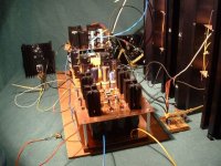
The way I described it to my wife was that I wanted to take these pictures in the same way that you would a pig in a bikini. So we used a green backdrop and tried to light things nicely, etc.
Okay, so it's still a pig in a bikini. As I detailed elsewhere, my plans to get myself a nice chassis made ran afoul of reality.
I've never tried to post a picture here, so this may or may not work. There should be two pictures--one of the whole amp and one of the front end.
Grey
Okay, so it's still a pig in a bikini. As I detailed elsewhere, my plans to get myself a nice chassis made ran afoul of reality.
I've never tried to post a picture here, so this may or may not work. There should be two pictures--one of the whole amp and one of the front end.
Grey
Attachments
- Status
- This old topic is closed. If you want to reopen this topic, contact a moderator using the "Report Post" button.
- Home
- Amplifiers
- Solid State
- The GR-25