Grey, thanks for reminding me that the damping factor is just another word for output impedance!
So around 20 per pair of vertical fets with 0.2R source resistors.
Nelson always points out that total bias is of interest, not the bias per part. So by paralleling some pairs (gets also dissipation per part down and reliability up), one could arrive at about 80 using say 4 pairs, even more with lower source resistors (but this increases distortion so maybe stick with the 0.2R). Really not bad I would say.
By the way, where's the master? While you're at it, a pic with the creator of his little creature would also be nice! Maybe with the fearless Cindi as well, if she doesn't mind a bit online popularity!
Have fun, Hannes
PS: looking at the X5, one is puzzled with the improvement NFB brings. The X5 sports a damping factor of 200, having 4 output pairs with 0.47R source resistors - without feedback it should be about 50.
 javascript:smilie('
Damping factor is a little more complicated than just tallying up the Source resistors and dividing. The Source adds its own contribution and to get a good idea of that figure, you have to know the device type and how hard they're biased. An ideal device would have a Source impedance of 0 Ohms. If anyone has a box of ideal devices to spare, I'd appreciate it if you'd send them to me. Lacking ideal devices, the real ones have some impedance. I just pulled up the datasheet for the FQA19N20C. The Rdson is listed as .17 Ohms. On one hand, I'm not biasing the devices as hard as Fairchild is, so it'll be higher. On the other hand, their number could be a little optimistic. I probably overstated the case by saying that the Source resistors dominated the output impedance. They're probably more like a third to half. Nelson has told of some way to measure the Zout of an amp using another amp to drive it, but I don't remember the details and I don't have time to hunt it down at the moment.
The reason I don't get all twitterpated about the damping factor is that it's considerably overrated as a number. My old Conrad Johnson Premier One (a tube amp) had a fairly low damping factor, but it simply stomped most solid state amps in the low end. That plus the fact that damping factor is a diminishing returns sort of thing (Is a damping factor of 10000 really 100 times better than a damping factor of 100? I don't think so.) kinda puts it in the category of THD for me. Is it important? Yeah...up to a point...after which your time is better spent working on other problems. Like I said above--5% distortion in a subwoofer? Great time to employ feedback. That much distortion is a serious problem and feedback is the tool for the job. Damping factor of 1? Hmmm...not so good. Damping factor of, say, 20 or 50? Okay, let's take a look at something else and maybe we'll come back to the damping factor thing later if it seems like it needs more attention. If you match your devices well, you can use lower value Source resistors and get a lower Zout that way. Or you can parallel more devices. Or you can bias harder. Or you can add feedback. Or you can just sit back with some Highland Park 18 or a good Bordeaux and listen. I vote for the latter option.
What on earth do you want a picture of me for? Just go look at a picture of Shrek. Envision me as his older, uglier, and meaner brother. With even worse social skills. I sent Nelson a picture that happened to have me in it once upon a time. He commented that I 'didn't look as old as I write.'
Maybe I should figure out how to 'write younger.'
Grey
P.S.: According to the textbooks, an ideal device would have infinite input impedance, 0 Ohms Source impedance, and infinite gain (which actually proceeds naturally from the 0 Ohms if you work the math angle). Speaking solely for myself, I'd trade infinite gain for linear gain any day of the week. Finite gain suits me just fine. Personally, I think the guys who write the textbooks need their head examined. Yes, yes, I know...the assumptions for the ideal device include the use of infinite feedback to linearize the silly thing. But if we're wishing for an ideal device, let's take a look at the intended application before wishing for the wrong parameters. You know that old expression? The one that says: Be careful what you ask for, you just might get it. At least for audio purposes, I think the wish list should be modified.
Thanks Grey for replying, it was only meant as a rough estimate as you weren't to be pushed for numbers. Numbers have quantitative quality and have more meaning to me than when you simply say, damping is low. What means low? I guess everybody has a different measure for that.
If it's say 50, I'm perfectly happy. Same with THD, personally I want that odd number below 1% - where it is exactly I do not care that much. Same with IMD. But I want to know.
Why do we want to see a picture from you? Dunno, to assign a face to work - why not? You could always hold one of your books and push your sales
All the best, Hannes
By the way, I still haven't said it yet: I consider your GR25 a really mean amp. With THD below 1% at full output, damping at 50 it has very reasonable specs and that without any NFB. I haven't seen another feedback-free amp with such specs and I'm sure it sounds marvelous.
I'm just waiting that the NFB-crowd kicks in and makes some pcbs (so that I don't have to tear myself apart - again).
All the best, Hannes
PS: Grey, you told me to remind you to fetch your post-it with THD at full output. Give the beancounters their kick - thank you!
I'm just waiting that the NFB-crowd kicks in and makes some pcbs (so that I don't have to tear myself apart - again).
All the best, Hannes
PS: Grey, you told me to remind you to fetch your post-it with THD at full output. Give the beancounters their kick - thank you!
Grey,
The notion that Rds_on has something to do with Zout is a misconception. Mr.Bob Cordell and others have written a few post on how the output impedance of a source/emitter follower is made up (pls read here and here)
Zout = (Rs + 1/gm_Nch) // (Rs + 1/gm_Pch) under class A conditions. When you enter class B one of the terms falls out of the equation (the one that belongs to the FET that goes into cutoff).
The 19N20 is quite like a IRFP240 and will have a gm of about 2..3S at the 1.3A you're running it at. This also is close to Bob's rule of thumb that the FET gm is roughly 1/10th of BJT gm at the same current (a BJT at 1.3A would weigh in at 50S). So your output stage might have about 0.1..0.2 Ohms (which seems to relate nicely to your DF=50@8R value). There is nothing wrong with that, I myself am not the high damping factor camp, of much greater concern is how constant it is (as any dynamic change of Zout IS plain distortion). So the trick is to find a bias current where the Zout is as constant as possible over the widest output current swing. See also the D2S discussion, where the goal is to have true constant gm at least in the most important low level region.
Measuring bulk output impedance is easy, drive the output of the amp (which has no signal applied) with another amp/channel via a bigger resistor, say 100Ohms or so, this practially is a current source with Iout=Vout/100. Measure the AC voltage at the DUT, say 10mV with 10V drive (=100mA), so Zout is 10mV/100mA=0.1Ohm. You can further drive the DUT amp with DC to have a standing output current underlying and can then get small signal Zout at varying output current and will probably find that Zout is lower at larger output currents, because gm increases greatly with current.
A counterchecking test is to drive to different loads and the obtain the Zout from the voltage and resistor ratios:
Say you have V1 with R1 and V2 with R2,
then set ratios v=V1:V2 and r=R1:R2,
and get
Rout = R1 * (1/v - 1) / (1 - r/v)
This one has less precision especially when the r/v ratio is close to unity. You must load the amp quite differently but not to lightly to get stable results.
Last not least I have to say that I like your design, especially the frontend.
- Klaus
Mr GJ Rollins has been cloned, pretty unusual for a tube gent to even skip the impedance of the PS.
Does the South Carolina University have a vast supply of 2SJ313/2SK2013 ?
Toshiba stil manufactures the duo, but mere mortals will have a hard time buying them in <<1K numbers.
Does the South Carolina University have a vast supply of 2SJ313/2SK2013 ?
Toshiba stil manufactures the duo, but mere mortals will have a hard time buying them in <<1K numbers.
KSTR said:Grey,
The notion that Rds_on has something to do with Zout is a misconception.
...So your output stage might have about 0.1..0.2 Ohms (which seems to relate nicely to your DF=50@8R value).
One of the things that's particularly murky about building your own class A amp is how big a power transformer to buy. Folks who are new to DIY get panicky when they hit this particular question and I'm completely sympathetic. I was a little perplexed when I first faced the question, myself.
Once upon a time, a new member asked how big a transformer to buy for an Aleph 2 (100W/ch class A monoblock). I replied, "Oh, that's easy. For Alephs, you just buy a transformer that's rated for six times the output wattage of the amp. For an Aleph 2, that would be 600VA." Whereupon, someone indignantly posted that I was wrong--the actual answer was...and he proceeded to burn incense, draw pentagrams on the floor, and pray to the audio gods to hear his humble plea for an answer...he then performed nine hundred and ninety-nine intricate calculations, followed by the sacrifice of a newborn lamb under a crescent moon. Then with great satisfaction, he pronounced the answer to be...(no, not 42)...579.
Ahem.
I submit that for all practical purposes 579=600, particularly in a world where transformer manufacturers tend to offer transformers in multiples of 50 or 100VA.
You've gone to a lot of trouble to come up with pretty much the same number you'd have gotten if you simply added the Rdson to the value of the Source resistors, then divided by the number of devices. I dunno about you, but for a simple-minded Southern boy, my way seems easier. I've got limited time, and anything that quickly gives me a reasonable answer is the method of choice. If I've only got an hour a week (a fairly reasonable average), spending it calculating isn't anywhere near as productive as spending it soldering. I want something I can listen to--not a piece of paper with three dozen scrawled calculations. My hearing is pretty good, but not good enough that I can hold a sheet of paper to my ear and hear music. Not even if it's a musical score. Maybe I should just turn up the volume...
Granted, the difference between .1 and .2 Ohms at the output is a factor of two and it might, arguably, make a difference whether the damping factor is 30 or 60 to some people. By now fifty people have probably simulated this circuit and if you ask any ten of them, you'll get twelve answers. If it's going to turn into a bother, I'll try to measure it directly at some point so we'll know, but it'll probably have to wait until next weekend at the earliest.
Bear in mind that we'll have to set some boundaries on the problem because I use different Source resistors depending on which bias circuit I'm using. For instance, the auto-bias circuit sets Vbe across the Source resistors and tends to require something along the lines of .5 Ohms. Obviously this is going to change things. I've also got some intermediate value parts--right now the amps have .33 Ohms in them, for instance, that I use when I'm changing things around and might smoke something. I regard those .33 Ohm resistors as sacrificial. If they go poof! I won't be bothered because they didn't cost me anything.
Don't thank me, thank John. It's his topology. I'm just borrowing it.
Grey
jacco vermeulen said:
...2SJ313/2SK2013 ?
Toshiba stil manufactures the duo, but mere mortals will have a hard time buying them in <<1K numbers.
I got mine from www.bdent.com. You might also try MCM, ceitron, et. al. For overseas...man, I don't know what to say. You guys always seem to be able to get things we can't easily get here in the US, so I figured you'd be able to track down Toshiba parts. Maybe someone will come up with a suggestion for a European source.
Grey
GRollins said:For instance, the auto-bias circuit sets Vbe across the Source resistors and tends to require something along the lines of .5 Ohms.
I don't recall seeing this in your schematic.
GRollins said:can't easily get here in the US
Half true, <50 nations in less square miles than 50 states leaves more residue.
For an example of the second half, type in Centerpoint Electr. in Cyprus Californi-ey for the 2SK. (CPCares)
(pretty boards, appealing soldering fingerprints)
Nelson,
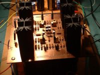
No, the auto-bias is a separate bias circuit, similar to the one you and I were discussing at some point last fall; a fairly straight-forward variation of John's double Vbe multiplier. The one in the schematic is the one that's on the amps now and also in the picture of the whole amp--it's the small circuit board to the right, between the heatsinks and the main circuitry. I try to make things as modular as possible so I can swap in parts--such as bias circuits--that happen to be of interest to me at the moment. Bias is one such thing.
I'm very interested in automating the bias for the circuit. I've got that one auto-bias circuit up and running and two or three more ideas that I want to try as time permits. I know you've got several bias circuits that you've been thinking about, so to that extent our interests coincide at the moment.
Curiously, the overload behavior of the auto-bias circuit is worse than the bias circuit in the schematic. I haven't had time to sit down and think that one through. It'll be something simple.
Grey
The Line Drive
John is John. He will post in this thread or not, depending on how he feels about things.
In the meantime...
Suppose you're interested in a no-feedback line stage to go along with the amp. Also suppose you can do without gain because your CD player and your phono stage both have enough output to drive your amplifier to reasonable volumes directly. What would you do?
Well, you'd go for a so-called passive preamp, wouldn't you? Or maybe not. After all, passive preamps are schizophrenic. They're torn between having a low enough impedance not to cause problems with cables, while at the same time having a high enough impedance not to unduly load the source. The simplicity and purity of the concept are seductive, but the reality leaves you wanting.
Now let's say you're willing to make a little, bitty compromise...enough to allow a couple of JFETs to sneak in the back door. If you could see your way clear to doing that much, there's an easy way to have your cake and eat it too.
The circuit I call the Line Drive is a bone-headedly simple circuit; you use a self-biasing JFET follower behind--and ahead of, if you want--your volume control. Ta da! Both input and output impedance problems are solved.
(Surely someone has posted a circuit like this...it's so dead simple that there should be a dozen competing versions, but I can't recall seeing one.)
JFETs being JFETs, for all practical purposes you've got infinite impedance at the Gate. You can set your input impedance to any value you want by choosing a reasonable value for R1. I put 100k because that's a comfortable value to anyone who is used to tubes. If you think 10k sounds better, be my guest, use 10k. The buffer is comprised of one (or more--I show two pairs in parallel for extra current) pair of JFETs. One N-ch and one P-ch. Tie the Gates together and bias them with smallish resistors under their Sources. The pot between them is there to zero the residual DC offset. Depending on how well your N-ch and P-ch JFETs are matched to each other you might need to use a larger value pot. That's easy to tell--if you run out of adjustment before the DC is set to zero, then try the next higher value. Otherwise, use as small a pot as you can, leaving the bulk of the resistance to the fixed resistors. As with the amplifier, DC offset from that point on is primarily a question of keeping the temperature of the JFETs constant.
You can substitute the usual suspects for the 2SK246/2SJ103 if you want: 2SK389/2SJ109 or 2SK170/2SJ74 are excellent choices. Feel free to experiment. Just match the N-ch devices to each other and the P-ch devices to each other. Do the best you can (I know it's not always easy) to match the N devices to the P devices. If you can't get them matched, use a bigger pot and everything will be fine.
The schematic shows two JFET buffers with the volume control sandwiched in between. If your source is happy with the load presented by your volume pot, you can leave out the first buffer. If your volume control is really close to your amplifier, you might be able to dispense with the buffer after the volume control.
As far as the volume pot goes, you can use anything you want. Penny & Giles, Radio Shack, optocoupler (e.g. Lightspeed), the constant load 10k binary relay widget the fellow posted a few years ago...that's the whole point. You can use anything without fear of loading problems.
Go ahead and build a few extras while you're at it. The circuit also works perfectly as an active crossover building block. Put your RC filter between the two buffers and you'll get textbook curves first time, every time.
Grey
Attachments
- Status
- This old topic is closed. If you want to reopen this topic, contact a moderator using the "Report Post" button.
- Home
- Amplifiers
- Solid State
- The GR-25